SERVICE MANUAL MODEL VFB2 ELECTRIC COUNTER-STYLE FLASHBAKE® OVEN ML 126582 - NOTICE This Manual is prepared for the use of trained Vulcan Service Technicians and should not be used by those not properly qualified. If you have attended a Vulcan Service School for this product, you may be qualified to perform all the procedures described in this manual. This manual is not intended to be all encompassing.
FLASHBAKE® OVEN GENERAL TABLE OF CONTENTS GENERAL . . . . . . . . . . . . . . . . . . . . . . . . . . . . . . . . . . . . . . . . . . . . . . . . . . . . . . . . . . . . . . . . . . . . . . . . . . . . . Introduction . . . . . . . . . . . . . . . . . . . . . . . . . . . . . . . . . . . . . . . . . . . . . . . . . . . . . . . . . . . . . . . . . . . . . . . . Electrical Specifications . . . . . . . . . . . . . . . . . . . . . . . . . . . . . . . . . . . . . . . . . . . . . . . . . . . . . . . . . . . . . .
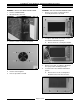
FLASHBAKE® OVEN GENERAL GENERAL INTRODUCTION OPERATION General ® The FlashBake oven is a versatile oven that employs a revolutionary high quality, high speed cooking technology. The baking process is so fast that food retains its natural juices. Bread products brown and become crisp while vegetables retain their color and texture. The texture, appearance and quality of food cooked in this oven is superior to that provided by any other method of cooking.
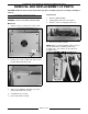
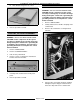
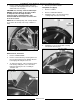
FLASHBAKE® OVEN REMOVAL AND REPLACEMENT OF PARTS REMOVAL AND REPLACEMENT OF PARTS CAUTION: Handle all reflective parts and interior door glass carefully to prevent scratching or marking of surfaces. Control Panel COVERS AND PANELS 1. Remove “MAIN COVER”. WARNING: UNPLUG THE MAIN POWER CORD. 2. Unplug ribbon cable from rear of panel. Main Cover 3. Remove screws securing panel from rear. 4. Reverse procedure to install. 1. Remove screws securing cover at rear of unit.
FLASHBAKE® OVEN REMOVAL AND REPLACEMENT OF PARTS FAN DOOR WARNING: UNPLUG THE MAIN POWER CORD. WARNING: UNPLUG THE MAIN POWER CORD. 1. Remove “MAIN COVER”. 1. 2. Disconnect wires from fan. Remove four screws securing outer door assembly and remove outer half. 2. To replace door handle, door latch or outer door window and window gasket: 3. Remove screws securing fan and guard. 4. Remove fan and guard. 5. Reverse procedure to install. A. Remove two bolts securing door handle. 3.
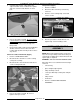
FLASHBAKE® OVEN REMOVAL AND REPLACEMENT OF PARTS B. Slide window and gasket out of door. CONTROL BOARD WARNING: UNPLUG THE MAIN POWER CORD. CAUTION: Certain components in this system are subject to damage by electrostatic discharge during field repairs. a field service grounding kit is available to prevent damage. The field service grounding kit must be used anytime the control board is handled. 5. Reverse procedure to install. 1. Remove “MAIN COVER”. 2.
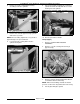
FLASHBAKE® OVEN REMOVAL AND REPLACEMENT OF PARTS 5. Squeeze tabs on standoffs and push standoffs out of control board. 3. Insert new prom being sure orientation is correct. Insure that pins do not get bent. 4. Install main cover. UPPER LAMP HOUSING ASSEMBLY 6. NOTE: When upper lamp housing is removed for any reason, inspect lamp sockets and center post contact plate for pitting due to bad connections and replace parts as required. Reverse procedure to install. WARNING: UNPLUG THE MAIN POWER CORD.
FLASHBAKE® OVEN REMOVAL AND REPLACEMENT OF PARTS 6. Remove 4 screws securing upper housing assembly to reflective cylinder. 7. Remove nuts on both upper housing eye bolts and remove eye bolts. 9. NOTE: On reassembly, tighten nuts on eye bolts to approximately 3/4" exposed threads. 8. Loosen two nuts securing both reflective cylinder cinch plates. Lift rear of housing assembly out of reflective cylinder and then carefully work the rest of the housing out of the cylinder. 10.
FLASHBAKE® OVEN REMOVAL AND REPLACEMENT OF PARTS 5. Remove lamps by pushing lamps away from center post to disengage them from center post and then lift out of housing. CAUTION: Use clean dry cloth to handle lamps. DO NOT get finger prints or any other residue on lamps because the lamp life will be shortened. Clean cold lamps with a cloth moistened with alcohol cleaner to remove skin oil or other residue. 4. Reverse procedure to install. Lamp Reflector (Upper) 1. Remove “LAMPS”. 2.
FLASHBAKE® OVEN REMOVAL AND REPLACEMENT OF PARTS 5. Carefully work reflector out by lifting outer edges to enable center of reflector to separate and come out from under washer on center post. 6. Reverse procedure to install. Be sure reflector is under washer on center post before reflector tabs are bent. If not under washer, there will not be sufficient clearance to insert lamps into lamp socket. 7. Clean reflector with a cloth moistened with Blue Shower cleaner to remove skin oil or other residue.
FLASHBAKE® OVEN REMOVAL AND REPLACEMENT OF PARTS 2. Remove 1 screw on each side and remove air deflector. 3. Loosen 1 screw each side securing reflective cylinder to lower lamp housing. 4. Remove nut on eye hook on each side. 5. Remove “DOOR LATCH”. 6. Remove 2 reflective cylinder cinch plate nuts on each side. 10. Remove 2 nuts and washers securing lower housing bracket to base of unit. 11. Disconnect lower lamp housing wires and plugs from control board. 12.
FLASHBAKE® OVEN REMOVAL AND REPLACEMENT OF PARTS Lamps (Lower) 1. Perform removal procedure “LOWER LAMP HOUSING ASSEMBLY” steps 1 thru 9. 2. Remove lamps by pushing lamps away from center post to disengage them from center post and then lift out of housing. 4. Remove exhaust ducts by releasing tab in slot. Press from inside duct in an outward direction to disengage tab and pull out of slot. 5. Straighten 4 tabs (1 in each air passage) securing lamp reflector to housing. 6.
FLASHBAKE® OVEN REMOVAL AND REPLACEMENT OF PARTS 7. Carefully work reflector out by lifting outer edges to enable center of reflector to separate and come out from under washer on center post. 8. Reverse procedure to install. Be sure reflector is under washer on center post before reflector tabs are bent. If not under washer, there will not be sufficient clearance to insert lamps into lamp socket. 9. Clean reflector with a cloth moistened with Blue Shower cleaner to remove skin oil or other residue.
FLASHBAKE® OVEN REMOVAL AND REPLACEMENT OF PARTS 12. Press door bumper tabs into cutouts in latch assembly. DOOR LATCH ASSEMBLY WARNING: UNPLUG THE MAIN POWER CORD. 1. Remove “MAIN HOUSING”. 2. Remove top nuts and loosen bottom nuts securing latch assembly to unit. 3. Pull latch assembly rearward to release door bumper and lift assembly off lower mounting studs. 4. To change solenoid, remove screws securing it. 5. Cut wire tie and disconnect wires from harness. 6. Remove screws securing switch.
FLASHBAKE® OVEN SERVICE PROCEDURES AND ADJUSTMENTS SERVICE PROCEDURES AND ADJUSTMENTS DOOR SWITCH WARNING: UNPLUG THE MAIN POWER CORD. When in a cook cycle, the door switch should not operate before the latch pawl contacts the energized solenoid pawl lock. 1. Perform steps 1 thru 3 in removal procedure “DOOR LATCH ASSEMBLY”. NOTE: Picture below shows latch pawl in the open door position. 2. Manually move latch pawl to “door closed position”. Switch is operated. 3.
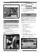
FLASHBAKE® OVEN SERVICE PROCEDURES AND ADJUSTMENTS SERVICE DIAGNOSTICS a. The display will report the values at the end of a 7 second test. Values reported for REFL, VOLT and TEMP should be between zero and 255. Values should not be zero or 255. b. Ignore the values on the right side of the display. To enter service diagnostics: 1. Remove “MAIN HOUSING”. 2. Unplug power cord. 3. Install jumper on JP103 on control board. 4. Set selector knob to Brown. 5. Plug unit in. 6.
FLASHBAKE® OVEN SERVICE PROCEDURES AND ADJUSTMENTS 3) If value is out of range, adjust R99 on the control board. Turn clockwise to increase the value, counterclockwise to decrease the value. NOTE: Readings do not change if you adjust R99 while watching display. The unit must go thru the 15 second test to display a new value. The potentiometer is sensitive so only turn it about 1/8 turn or less at one time. 8. Press Start. 9. After 15 seconds, press Save. 10. Check the values reported on the display.
FLASHBAKE® OVEN ELECTRICAL OPERATION ELECTRICAL OPERATION COMPONENT FUNCTION F1 FUSE . . . . . . . . . . . . . . . . . . . . . . . . . Protects transformer and fan. FAN . . . . . . . . . . . . . . . . . . . . . . . . . . . . Moves air across lamps to help cool lamp area. THERMOSTATS . . . . . . . . . . . . . . . . . . Protects oven cavity from overheating. Monitors temperature in upper lamp housing and in lower lamp housing. Opens at 200(F (± 5); auto reset at 170(F (± 5). DOOR SWITCH . . . . . . . .
FLASHBAKE® OVEN ELECTRICAL OPERATION COMPONENT LOCATION Page 19 of 24
FLASHBAKE® OVEN ELECTRICAL OPERATION CONTROL BOARD LAYOUT Page 20 of 24
FLASHBAKE® OVEN ELECTRICAL OPERATION SCHEMATIC DIAGRAM Page 21 of 24
FLASHBAKE® OVEN ELECTRICAL OPERATION WIRING DIAGRAM Page 22 of 24
FLASHBAKE® OVEN ELECTRICAL OPERATION 8. SEQUENCE OF OPERATION Oven reverts back to conditions in step 2. Operation Monitor 1. A. Correct voltage to oven on control board. B. Power fuse good. C. Building Circuit breakers closed. The unit uses the control board to monitor the status of certain points on the oven. If the status of any point is not within normal operating conditions a message is reported and the relay on the control board which powers the lamps may be deenergized. D.
FLASHBAKE® OVEN TROUBLESHOOTING TROUBLESHOOTING ERROR MESSAGES MESSAGE Oven can not operate. Oven is overheated. Oven can not operate. Door is not closed. SYMPTOM Oven does not operate. Oven does not enter a cook cycle and displays error messages. Fan continues to run after cook cycle is completed. NOTE: It is normal for fan to run a while (approximately 4 minutes maximum) after a cook cycle ends to cool down lamp housings. Fan never runs. Display does not light up/no characters displayed.