SERVICE MANUAL MODEL VSX3E SHOWN VSX SERIES CONVECTION STEAMERS (ELECTRIC AND GAS) VSX3E VSX3E VSX4E VSX5E VSX7EC VSX7EO ML-52396 ML-52397 ML-52398 ML-52399 ML-114822 ML-114821 VSX10EC VSX10EO VSX5G VSX5GC VSX7GC VSX10GC ML-114824 ML-114823 ML-114946 ML-114947 ML-114949 ML-114949 - NOTICE This Manual is prepared for the use of trained Vulcan Service Technicians and should not be used by those not properly qualified.
VSX SERIES STEAMERS TABLE OF CONTENTS GENERAL . . . . . . . . . . . . . . . . . . . . . . . . . . . . . . . . . . . . . . . . . . . . . . . . . . . . . . . . . . . . . . . . . . . . . . . . . . . . . Introduction . . . . . . . . . . . . . . . . . . . . . . . . . . . . . . . . . . . . . . . . . . . . . . . . . . . . . . . . . . . . . . . . . . . . . . . . Specifications . . . . . . . . . . . . . . . . . . . . . . . . . . . . . . . . . . . . . . . . . . . . . . . . . . . . . . . . . . . . . . . . . . . . . .
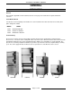
VSX SERIES STEAMERS -GENERAL GENERAL INTRODUCTION General This manual is applicable for all models listed on the cover page. Several models are pictured below for reference. Serial Number Break Listed below, are the beginning serial numbers for each model when the solid state water level control (three probe design) was added.
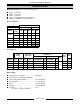
VSX SERIES STEAMERS -GENERAL SPECIFICATIONS Model Designations (based on 2.5 inch pan depth) VSX3 - 3 pan unit. VSX4 - 4 pan unit. VSX5 - 5 pan unit. VSX7 - Combination VSX3 and VSX4 unit. VSX10 - Combination of two VSX5 units. Electric Steamers AMPERAGE 3 PHASE MODEL VSX3E 1 PHASE TOTAL 208V 240V 480V 208V 240V KW 7.5 std. 20.9 18.1 9.0 36.1 31.3 10.0 opt. 27.8 24.1 12.1 48.1 41.7 VSX4E 10.0 27.8 24.1 12.1 48.1 41.7 VSX5E 15.0 41.6 36.2 18.1 72.2 62.5 VSX7E 17.
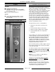
VSX SERIES STEAMERS -GENERAL TOOLS WATER CONDITIONING Standard Standard set of hand tools. VOM with an AC current tester (any quality VOM with a sensitivity of at least 20,000 ohms per volt can be used). Gas leak checking equipment. Special CLR Treatment Kit (p/n 817634) - Used to remove Calcium/Lime/Rust from a steam generator tank. CONTROL LOCATION Furnishing the steam generator with soft water to reduce scale formation is important.
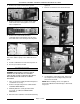
VSX SERIES STEAMER - REMOVAL AND REPLACEMENT OF PARTS REMOVAL AND REPLACEMENT OF PARTS B. Remove the screws that secure the flue to the tank and lift it off. COVERS AND PANELS WARNING: DISCONNECT THE ELECTRICAL POWER TO THE MACHINE AT THE MAIN CIRCUIT BOX. PLACE A TAG ON THE CIRCUIT BOX INDICATING THE CIRCUIT IS BEING SERVICED. Right Side Panel 1. Remove screws from the bottom of the panel. 2. Slide panel down to clear the top cover. 2.
VSX SERIES STEAMER - REMOVAL AND REPLACEMENT OF PARTS 2. Remove the screws at the bottom of panel. replaced. 5. Remove screws that secure the thermostat. 3. Remove the lower access panels on the right and left side of the unit to gain access to the lower compartment. 4. Remove the screws Inside the lower compartment that run along the top rear of the base frame that secure the lip of the rear panel.
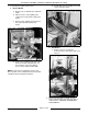
VSX SERIES STEAMER - REMOVAL AND REPLACEMENT OF PARTS 7. If replacing the high limit thermostat: 5) Pull the bulb from its holding sleeve and remove from the heater. A. Electric Models 1) Remove nut on capillary tube hold down clamp. 2) Fully loosen the small capillary tube compression nut and slide it away from heater. 3) Remove large capillary nut from heater base plate and slide it away from heater. B. Gas Models 1) Remove the nuts securing the thermostat to the tank surface plate and lift it off.
VSX SERIES STEAMER - REMOVAL AND REPLACEMENT OF PARTS 5. Remove the nuts that secure the heater to the tank and remove the heater from the unit. TIMER WARNING: DISCONNECT THE ELECTRICAL POWER TO THE MACHINE AT THE MAIN CIRCUIT BOX. PLACE A TAG ON THE CIRCUIT BOX INDICATING THE CIRCUIT IS BEING SERVICED. 1. Remove the right side panel as outlined under "COVERS AND PANELS". 2. Pull timer knob from shaft. 3. Disconnect lead wires to timer. 4. Remove nut from timer shaft and remove timer from the unit. 6.
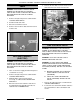
VSX SERIES STEAMER - REMOVAL AND REPLACEMENT OF PARTS 3. Loosen the compression nuts on the flexible gas line then remove line from the gas solenoid valve and manifold. B. Loosen the compression nuts on the “condenser feed” and “tank feed” water lines and place the lines to the side. NOTE: If necessary, loosen the remaining compression nut on the “cold water condenser” solenoid and rotate it out of the way. 6. Open the lower cabinet base door to gain access the gas solenoid valves. (VSX5G SHOWN) 4.
VSX SERIES STEAMER - REMOVAL AND REPLACEMENT OF PARTS GAS PRESSURE REGULATOR FLAME SENSE PROBE (GAS) WARNING: DISCONNECT THE ELECTRICAL POWER TO THE MACHINE AT THE MAIN CIRCUIT BOX. PLACE A TAG ON THE CIRCUIT BOX INDICATING THE CIRCUIT IS BEING SERVICED. WARNING: DISCONNECT THE ELECTRICAL POWER TO THE MACHINE AT THE MAIN CIRCUIT BOX. PLACE A TAG ON THE CIRCUIT BOX INDICATING THE CIRCUIT IS BEING SERVICED. WARNING: SHUT OFF THE GAS SUPPLY BEFORE SERVICING THE UNIT.
VSX SERIES STEAMER - REMOVAL AND REPLACEMENT OF PARTS HOT SURFACE IGNITOR (GAS) GAS BURNER WARNING: DISCONNECT THE ELECTRICAL POWER TO THE MACHINE AT THE MAIN CIRCUIT BOX. PLACE A TAG ON THE CIRCUIT BOX INDICATING THE CIRCUIT IS BEING SERVICED. WARNING: DISCONNECT THE ELECTRICAL POWER TO THE MACHINE AT THE MAIN CIRCUIT BOX. PLACE A TAG ON THE CIRCUIT BOX INDICATING THE CIRCUIT IS BEING SERVICED. WARNING: SHUT OFF THE GAS SUPPLY BEFORE SERVICING THE UNIT. 1.
VSX SERIES STEAMER - REMOVAL AND REPLACEMENT OF PARTS GAS IGNITION MODULE WARNING: DISCONNECT THE ELECTRICAL POWER TO THE MACHINE AT THE MAIN CIRCUIT BOX. PLACE A TAG ON THE CIRCUIT BOX INDICATING THE CIRCUIT IS BEING SERVICED. 3. Manually drain steam generator tank if necessary, as outlined under "DRAIN TANK MANUALLY". 4. Disconnect the lead wire from each water level probe and then remove probes from tank. Mark probes accordingly for replacement. 1.
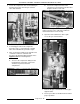
VSX SERIES STEAMER - REMOVAL AND REPLACEMENT OF PARTS 5. Disconnect the steam lines on the top right and left side of the tank, the water fill tube, the drain line, then the delime line at the bottom left corner. 7. Gas Model Only A. Remove the burner assembly and place to the side. B. Remove the bolts that secure the manifold to the burner box frame and place to the side. C. Remove the surface high limit and the control thermostat bulb from the tank. D.
VSX SERIES STEAMER - REMOVAL AND REPLACEMENT OF PARTS 3. Unscrew probes from steam generator tank. 3. Cut the wire ties around “wire bundle” and trace the power wires for the solenoid valve being serviced back to there terminations and remove. 4. Disconnect the fittings on each side of the valve and remove the valve from the unit. 5. Reverse procedure to install. (Gas Model Shown) NOTE: Probe should be cleaned thoroughly. Remove all accumulated deposits from the insulator using a soft cloth.
VSX SERIES STEAMER - REMOVAL AND REPLACEMENT OF PARTS 5. Use a hammer and punch to turn the stem counterclockwise to remove the stem from the body. DRAIN VALVE WARNING: DISCONNECT THE ELECTRICAL POWER TO THE MACHINE AT THE MAIN CIRCUIT BOX. PLACE A TAG ON THE CIRCUIT BOX INDICATING THE CIRCUIT IS BEING SERVICED. Removal 1. Turn “off” the water supply to the steamer. 2. Remove the right side panel and top cover as outlined under "COVERS AND PANELS". 3.
VSX SERIES STEAMER - REMOVAL AND REPLACEMENT OF PARTS 5. Loosen the screws from the motor assembly and lift up on the motor to remove it from the valve body. NOTE: When re-installing, place flat sides of ball stem perpendicular to the inlet and outlet of the drain valve. The valve will be in the open position whenever power is removed from the motor. 6. Remove the screws from the cover plate and remove the cover plate and ball assembly from the valve body. 7. Reverse procedure to install.
VSX SERIES STEAMER - REMOVAL AND REPLACEMENT OF PARTS Gasket DOOR WARNING: DISCONNECT THE ELECTRICAL POWER TO THE MACHINE AT THE MAIN CIRCUIT BOX. PLACE A TAG ON THE CIRCUIT BOX INDICATING THE CIRCUIT IS BEING SERVICED. Removal 1. Remove top cover as outlined under "COVERS AND PANELS". 2. Open the door. 3. Pull hinge rod up. 1. Open the door. 2. Remove screws from the gasket plate. 3. Pull the gasket plate out from the door housing and remove the gasket. 4.
VSX SERIES STEAMER - REMOVAL AND REPLACEMENT OF PARTS Handle Latch Assembly 1. Open the door. 1. Open the door. 2. Remove screws from the top and bottom of the door. 2. Remove screws from the top and bottom of the door. 3. Pull the “inner” door panel out from the door housing with the gasket plate and gasket still attached. 3. Pull the “inner” door panel out from the door housing with the gasket plate and gasket still attached. 4.
VSX SERIES STEAMER - SERVICE PROCEDURES AND ADJUSTMENTS SERVICE PROCEDURES AND ADJUSTMENTS WARNING: CERTAIN PROCEDURES IN THIS SECTION REQUIRE ELECTRICAL TEST OR MEASUREMENTS WHILE POWER IS APPLIED TO THE MACHINE. EXERCISE EXTREME CAUTION AT ALL TIMES. IF TEST POINTS ARE NOT EASILY ACCESSIBLE, DISCONNECT POWER, ATTACH TEST EQUIPMENT AND REAPPLY POWER TO TEST. STEAM GENERATOR CLEANING NOTE: Factory default time set on the board is 100 hrs.
VSX SERIES STEAMER - SERVICE PROCEDURES AND ADJUSTMENTS 2. Turn the thermostat adjustment stem fully clockwise for a starting position. MODEL APPROXIMATE TIME FOR STEAM TO ENTER COMPARTMENT ELECTRIC 5 sec. GAS 13 sec. NOTE: If after increasing the thermostat setting, the ready light stays “on” (heat not on) then the thermostat is still satisfied.
VSX SERIES STEAMER - SERVICE PROCEDURES AND ADJUSTMENTS DOOR SEALING ADJUSTMENT To adjust: 1. Reinstall the striker with the slot pointing upwards and “hand tighten” nut only. 1. Check the door gasket quality. If damaged or worn, replace as outlined under “DOOR”. 2. Loosen screws until the screw heads no longer touch the gasket plate. 3. Tighten screws until screw head touches gasket plate and at that point begin counting turns. 4. Tighten all screws approximately two turns. 2.
VSX SERIES STEAMER - SERVICE PROCEDURES AND ADJUSTMENTS minimum stated, then the manifold pressure can not be set correctly. MANIFOLD PRESSURE ADJUSTMENT WARNING: DISCONNECT THE ELECTRICAL POWER TO THE MACHINE AT THE MAIN CIRCUIT BOX. PLACE A TAG ON THE CIRCUIT BOX INDICATING THE CIRCUIT IS BEING SERVICED. 6. Once the correct pressure has been set, turn the power switch “off”, replace the adjustment screw cap and manifold pipe plug. 7. Check unit for proper operation.
VSX SERIES STEAMER - SERVICE PROCEDURES AND ADJUSTMENTS FLAME SENSE PROBE (GAS) WARNING: THE FOLLOWING STEPS REQUIRE POWER TO BE APPLIED TO THE UNIT DURING THE TEST. USE EXTREME CAUTION AT ALL TIMES. 2. Perform a visual check to determine if the flame sense probe is in the upper portion of flame. If the probe is bent or not in the upper portion of the flame then check for alignment and adjust as necessary. A.
VSX SERIES STEAMER - SERVICE PROCEDURES AND ADJUSTMENTS HOT SURFACE IGNITOR (GAS) 1. Check to see if hot surface ignitor is operating during ignition trial by: A. Visual verification - HSI should be heating up “glowing brightly” to ignite gas. B. Voltage verification - check for 24VAC to HSI termination on the edge connector to ground. HEATING ELEMENT (ELECTRIC) WARNING: THE FOLLOWING STEPS REQUIRE POWER TO BE APPLIED TO THE UNIT DURING THE TEST. USE EXTREME CAUTION AT ALL TIMES. 1.
VSX SERIES STEAMER - ELECTRICAL OPERATION ELECTRICAL OPERATION COMPONENT FUNCTION 1A Delime Timer Board . . . Tracks the cumulative cooking hours by using a current sensor to monitor current flow through the cold water condenser solenoid lead, then signal’s operator to perform delime procedure after the steamer has operated in cook mode for a preset number of hours. Buzzer . . . . . . . . . . . . . . . . . Signals end of cook cycle, must be turned “off” manually. 1CON & 2CON Heater Contactor . . . . . .
VSX SERIES STEAMER - ELECTRICAL OPERATION 1S Power Switch . . . . . . . . Controls electrical power to the control circuit and delime circuit. 2S Door Switch . . . . . . . . . . Removes electrical power to the timer when the door is opened and the control thermostat is open. 1SOL Fill Solenoid . . . . . . . Controls tank water supply. (normally closed valve, water flows when energized) 2SOL Cold Water Solenoid . Controls cold water supply going into drain to mix and condense exhaust steam.
VSX SERIES STEAMER - ELECTRICAL OPERATION COMPONENT LOCATION Electric Models VSX3E, 4E & 5E VSX7E & 10E Page 28 of 40
VSX SERIES STEAMER - ELECTRICAL OPERATION Gas Models VSX5G VSX 7G & 10G Page 29 of 40
VSX SERIES STEAMER - ELECTRICAL OPERATION WATER LEVEL CONTROL OPERATION The water level control (WLC) has line voltage across terminals 11 and 12 which powers the primary side of the transformer. The secondary side of the transformer provides power to the control by a series path through chassis ground; through the water in the steam generator tank; through the water level probes; to the internal relay coils on the control.
VSX SERIES STEAMER - ELECTRICAL OPERATION A. Product is inserted into steamer. A. LLCO energizes. B. Door is closed. 1) Contacts LLCO-1 open; LLCO-2 close. C. Time is dialed on the timer. 2) LLCO LED lights. 3. Contacts 1/3 of timer close. 4. Water reaches LL (Low Level) probe. A. 1CON and 2CON are energized by the closing of 1TR 1/3 contacts and thru 2K-2 NC/C contacts. 5. Water reaches HL (High Level) probe. A. Internal relay HL energizes. B. HL LED lights.
VSX SERIES STEAMER - ELECTRICAL OPERATION A. Internal relay HL energize. DELIME CYCLE B. HL LED lights. 1. Steamer is in a cook cycle where the delime board monitors the cook time. C. Internal relay coil HL locks through HL-1. 6. 1SOL de-energized; water flow off. 2. Delime light comes on. A. After the initial fill, the water level is maintained by 1SOL being energized when the water level drops below the LL probe and being de-energized when the water level reaches the HL probe.
VSX SERIES STEAMER - ELECTRICAL OPERATION A. Power to pin 2 of water level control. COOK CYCLE 1. Cook cycle can not start until the initial fill and preheat is completed and the door is closed. 4. Water reaches high level probe. A. Internal coil HL of water level control is energized. A. 2K-1 (NC/C) contacts are open during preheat and will prevent operation of the timer, buzzer, 2SOL and 2LT. 1) WLC HL-2 opens. 2) WLC HL-3 closes. 2. Ready light lit. 3) WLC HL-1 close. A.
VSX SERIES STEAMER - ELECTRICAL OPERATION SCHEMATIC ELECTRIC STEAMERS Page 34 of 40
VSX SERIES STEAMER - ELECTRICAL OPERATION WIRING DIAGRAM ELECTRIC STEAMERS Page 35 of 40
VSX SERIES STEAMER - ELECTRICAL OPERATION SCHEMATIC GAS STEAMERS Page 36 of 40
VSX SERIES STEAMER - ELECTRICAL OPERATION WIRING DIAGRAM GAS STEAMERS Page 37 of 40
VSX SERIES STEAMER - TROUBLESHOOTING TROUBLESHOOTING ALL MODELS WARNING: CERTAIN PROCEDURES IN THIS SECTION REQUIRE ELECTRICAL TESTS OR MEASUREMENTS WHILE POWER IS APPLIED TO THE MACHINE. EXERCISE EXTREME CAUTION AT ALL TIMES. IF TEST POINTS ARE NOT EASILY ACCESSIBLE, DISCONNECT POWER, ATTACH TEST EQUIPMENT AND REAPPLY POWER TO TEST. SYMPTOM Compartment leaks water around door. POSSIBLE CAUSES 1. Unit not level. 2. Drain line obstructed or not to an open gap drain.
VSX SERIES STEAMER - TROUBLESHOOTING SYMPTOM Tank does not fill. POSSIBLE CAUSES 1. Water supply not on. 2. Fill solenoid 1SOL not opening or plugged. 3. Water level control malfunction (WLC). 4. Water level probes shorted to ground. Timer motor does not run. 1. Door open or door switch 2S inoperative. 2. 2K-1 NC/C contacts not closing. 3. Timer inoperative. Water running out of drain during fill or when the power switch 1S is off. 1. 1SOL stuck open.
VSX SERIES STEAMER - TROUBLESHOOTING GAS MODELS ONLY SYMPTOM Burner won’t light. POSSIBLE CAUSES 1. Gas not “on”. 2. Low incoming gas pressure. 3. HSI not operating see “HOT SURFACE IGNITOR” in “SERVICE PROCEDURES AND ADJUSTMENTS”. 4. Unit not properly grounded and/or polarity of incoming power is incorrect. 5. Ignition module not receiving power. Check 2T for 24VAC output to module. 6. Ignition module malfunctioning. Burner won’t stay lit. 1.