
Service manual


VSX SERIES STEAMER - REMOVAL AND REPLACEMENT OF PARTS
Page 9 of 40
TIMER
WARNING:
DISCONNECT THE ELECTRICAL
POWER TO THE MACHINE AT THE MAIN
CIRCUIT BOX. PLACE A TAG ON THE CIRCUIT
BOX INDICATING THE CIRCUIT IS BEING
SERVICED.
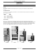
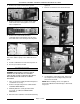
1. Remove the right side panel as outlined under
"COVERS AND PANELS".
2. Pull timer knob from shaft.
3. Disconnect lead wires to timer.
4. Remove nut from timer shaft and remove timer
from the unit.
5. Reverse the procedure to install.
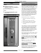
HEATING ELEMENTS
(ELECTRIC)
WARNING:
DISCONNECT THE ELECTRICAL
POWER TO THE MACHINE AT THE MAIN
CIRCUIT BOX. PLACE A TAG ON THE CIRCUIT
BOX INDICATING THE CIRCUIT IS BEING
SERVICED.
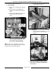
1. Turn “off” the water supply and allow hot parts to
cool down if necessary.
2. Remove the right side panel as outlined under
"COVERS AND PANELS".
3. Manually drain steam generator tank if
necessary, as outlined under "DRAIN TANK
MANUALLY".
4. Disconnect the heater lead wires and remove
the high limit thermostat bulb from heater as
outlined under “THERMOSTATS”.
5. Remove the nuts that secure the heater to the
tank and remove the heater from the unit.
6. Reverse procedure to install.
GAS SOLENOID VALVE
WARNING:
DISCONNECT THE ELECTRICAL
POWER TO THE MACHINE AT THE MAIN
CIRCUIT BOX. PLACE A TAG ON THE CIRCUIT
BOX INDICATING THE CIRCUIT IS BEING
SERVICED.
WARNING:
SHUT OFF THE GAS SUPPLY
BEFORE SERVICING THE UNIT.
WARNING:
ALL GAS JOINTS DISTURBED
DURING SERVICING MUST BE CHECKED FOR
LEAKS. CHECK USING A SOAP AND WATER
SOLUTION (BUBBLES). DO NOT USE AN OPEN
FLAME.
A. BEFORE LIGHTING UNIT, CHECK ALL
JOINTS PRIOR TO THE GAS VALVE
(SOLENOID).
B. CHECK ALL JOINTS BEYOND GAS
VALVE (SOLENOID) AFTER THE UNIT
HAS LIT.
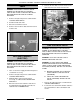
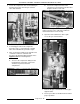
1. Remove the right side panel as outlined under
"COVERS AND PANELS".
2. Cut the wire ties around “wire bundle” and trace
the solenoid wires to
there terminations and
remove.