INSTALLATION INSTRUCTIONS AND OWNER’S MANUAL The Keystone "B" Vent Zero Clearance Gas Fireplace B-VENT GAS FIREPLACE MODEL SERIES MILLIVOLT BVD34FP30(F,L)N-1 BVD36FP32(F,L)N-1 BVP42FP32(F,L)N-1 DIRECT IGNITION GAS-FIRED BVD34FP50(F,L)N-1 BVD36FP52(F,L)N-1 BVP42FP52(F,L)N-1 EFFECTIVE DATE APRIL 2006 UL FILE NO. MH45034 Installer: Leave these instructions with the consumer. Consumer: Retain these instructions for future use.
TABLE OF CONTENTS Section Important Safety Information ....................................................................................................3 Safety Information for Users of LP Gas ....................................................................................4 Introduction ..............................................................................................................................5 Specifications ...........................................................................
IMPORTANT SAFETY INFORMATION Before enclosing the vent pipe assembly, operate the appliance to ensure it is venting properly. • If this appliance is installed directly on carpeting, tile or other combustible material other than wood flooring the appliance shall be installed on a metal or wood panel extending the full width and depth of the appliance. The base referred to above does not mean the fireproof base as used on wood stoves. The protection is for rugs that are extremely thick and light colored tile.
SAFETY INFORMATION FOR USERS OF LP GAS Propane (LP-Gas) is a flammable gas which can cause fires and explosions. In its natural state, propane is odorless and colorless. You may not know all the following safety precautions which can protect both you and your family from an accident. Read them carefully now, then review them point by point with the members of your household. Someday when there may not be a minute to lose, everyone’s safety will depend on knowing exactly what to do.
INTRODUCTION Instructions to Installer 1. Installer must leave instruction manual with owner after installation. 2. Installer must have owner fill out and mail warranty card supplied with the fireplace. 3. Installer should show owner how to start and operate the fireplace. This is a B-Vent gas appliance and must be installed with a listed B-Vent vent system. The information contained in this manual pertains to all models and gas control systems unless otherwise noted.
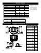
SPECIFICATIONS Input Btu/hr Maximum KWH (Maximum) B-Vent Size NAT. (Standard) Orifice Air Shutter Opening *LP (Conversion Kit Required) Orifice Air Shutter Opening Height without standoff Width Depth Gas Inlet Shutoff Valve (Pipe) BVD34FP 21,000 6.2 4" Diameter BVD36FP 25,000 7.3 6" Diameter BVP42FP 30,000 8.8 6" Diameter #44 (.086) P-252 1/8" (3.2mm) #42 (.0935) P-286 1/8"(3.2mm) #37 (.104) P-213 1/8" (3.2mm) 1.35mm P-289 5/16" (7.9mm) 32 3/4"(832mm) 37" (940mm) 14 7/8" (378mm) 1/2 NPT 1.
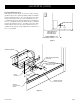
CLEARANCES Mantel Chart (Figure 3) Clearance to Combustibles Back 0" (0 mm) Side 0" (0 mm) Floor 0" (0 mm) Top Stand-off 0" (0 mm) Top Framing Edge 1" (25mm) 12” (305mm) 10” (254mm) MANTEL COMBUSTIBLE TRIM AND MANTELS ALLOWED IN SHADED AREA 8” 6” 12” 4 ½” SEE MANTLE CHART FOR MAXIMUM MANTLE DEPTH 3 3/4” 10 3/4” 3” 2 1/4” 2" x 4" HEADER 8” 1 ½” 3/4” 6” 5” STAND OFF 3" (76 mm) HEIGHT ABOVE TOP OF FIREPLACE SEE MANTLE CHART FOR MINIMUM HEIGHT OF MANTLE ABOVE UNIT 4” 3” 2” 1” TOP EDGE OF FIRE
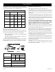
GAS SUPPLY The gas pipeline can be brought in through the right or left side of the appliance. Consult the current National Fuel Gas Code, ANSI Z223.1 CAN/CGA-B149 (.1 or .2) installation code. Recommended Gas Pipe Diameter Pipe Length (Feet) Schedule 40 Pipe Inside Diameter Tubing, Type L Outside Diameter Nat. L.P. Nat. L.P. 0-10 1/2" 12.7mm 3/8" 9.5mm 1/2" 12.7mm 3/8" 9.5mm 11-40 1/2" 12.7mm 1/2" 12.7mm 5/8" 15.9mm 1/2" 12.7mm 41-100 1/2" 12.7mm 1/2" 12.7mm 3/4" 19mm 1/2" 12.
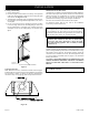
GAS SUPPLY (CONT) Checking Manifold Pressures Both Propane and Natural gas valves have a built-in pressure regulator in the gas valve. Natural gas models will have a manifold pressure of approximately 3.5" w.c. (.871kPa) at the valve outlet with the inlet pressure to the valve from a minimum of 4.5" w.c. (1.120kPa) for the purpose of input adjustment to a maximum of 14.0" w.c. (3.484kPa). Propane gas models will have a manifold pressure approximately 10.0" w.c. (2.
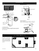
INSTALLATION Framing and Finishing 1. Choose unit location. 2. Frame in fireplace with a header across the top. It is important to allow for the finished face thickness when setting the depth of the frame. See Figures 9 & 11. 3. Attach fireplace to framing using (4) adjustable nailing flanges. Preset depth to suit facing material (adjustable to 1/2", 5/8" or 3/4" depths). 4.
INSTALLATION (CONT) Combustible Surround Installation MANTELSHELF COMBUSTIBLE SURROUND 2X4 HEADER STAND OFF FINISHED WALL FRONT TRIM OR NON-COMBUSTIBLE MATERIAL MAY OVERLAP BLACK PAINTED FACE (INSTALLATION IS OPTIONAL) JOINT BETWEEN FINISHED WALL AND UNIT SEALED WITH 300° F 149° C SEALANT MATERIAL (SEALANT IS OPTIONAL) Minimum Framing Dimensions BVD34 BVD36 BVP42 "A" 35 3/4" (908mm) 37 3/4" (959mm) 37 3/4" (959mm) "B" 37 3/8" (949mm) 39 3/8" (1,000mm) 43 3/8" (1,102mm) "C" 14 3/8" (378mm)
VENTING Vent Runs In planning the installation for the fireplace, it is necessary to install certain components before the appliance is completely positioned and installed. These include the vent system, gas piping for the appliance, Fresh Air Kit, and the electrical wiring. (The fan option is available for louvered models only. Electric ignition models will require electrical service to junction box). The appliance can be mounted on any of the following surfaces: 1.
VENTING (CONT) Offset Venting - With Elbows Vent Size Model BVD34FP series uses a 4" B-Vent for operation. Models BVD36FP and BVP42FP series use a 6" B-Vent for operation. Never downsize venting diameters. Maximum horizontal distance is 50% of vertical vent height Clearances Vent clearances are per vent manufacturer's specifications Vent Configuration Various venting configurations are shown in Figures 14 and 15 from which maximum vent runs can be determined.
LOG PLACEMENT (5 LOG SET) Before you begin: if you are installing logs into the BVD34 or BVD36 model, then this fireplace is supplied with a set of five ceramic fiber logs. Do not handle these logs with your bare hands! Always wear gloves to prevent skin irritation from ceramic fibers. After handling logs, wash your hands gently with soap and water to remove any traces of fibers. The positioning of the logs is critical to the safe and clean operation of this fireplace.
LOG PLACEMENT (3 LOG SET) Before you begin: If you are installing logs into the BVP42 model then this fireplace is supplied with a set of three ceramic fiber logs. Do not handle these logs with your bare hands. Always wear gloves to prevent skin irritation from ceramic fibers. After handling logs, wash your hands gently with soap and water to remove any traces of fiber. The positioning of logs is critical to safe and clean operation of this fireplace.
OPERATING INSTRUCTIONS 750 Millivolt System The standing pilot (750 millivolt system) is a continuous burning pilot. The pilot remains ON even when the main burner is OFF. The OWNER should carefully read and follow these operating instructions at all times. Lower the door assembly to view the gas controls for the fireplace. When you ignite the pilot, the thermopile produces millivolts (electrical current) which energizes the magnet in the gas valve.
OPERATING INSTRUCTIONS (CONT) STANDING PILOT OPERATING INSTRUCTIONS The fireplace is equipped with a 15 foot length of wire that can be used to connect the valve to a wall switch (installer provided) or remote control receiver. See instructions packed with each of the following optional switches or controls for proper installation, operation, and maintenance. Wall Switch, FWS-1 (optional) On millivolt valve models, a 15' wall switch wire is included.
STANDING PILOT WIRING DIAGRAM (OPTIONAL) REMOTE CONTROL RECEIVER (FACULTATIVE) CONTROLE E DISTANCE DU RECEPTEUR WALL SWITCH INTERRUPTEUR MURAL LIMIT SWITCH THERMOPILE IN PILOT V ENT GAS VALVE (OPTIONAL) THERMOSTAT (FACULATIVE) THERMOSTAT H PILOT VEILLEUSE N WALL SWITCH/REMOTE CONTROL RECEIVER/ THERMOSTAT CONTROLE E DISTANCE DU RECEPTEUR GAS VALVE VALVE DE GAZ Figure 23 Page 18 19400-3-0406
STANDING PILOT LIGHTING INSTRUCTIONS FOR YOUR SAFETY, READ BEFORE LIGHTING WARNING: IF YOU DO NOT FOLLOW THESE INSTRUCTIONS EXACTLY, A FIRE OR EXPLOSION MAY RESULT CAUSING PROPERTY DAMAGE, PERSONAL INJURY, OR LOSS OF LIFE A. This appliance has a pilot which must be lighted by hand. When lighting the pilot, follow these instructions exactly. B. BEFORE LIGHTING smell all around the appliance area for gas. Be sure to smell next to the floor because some gas is heavier than air and will settle on the floor.
STANDING PILOT TROUBLESHOOTING With proper installation and maintenance, your new Gas Fireplace will provide years of trouble-free service. If you do experience a problem, refer to the Trouble Shooting Guide below. This guide will assist a qualified service person in the diagnosis of problems and the corrective action to be taken. 1. Spark ignitor will not light pilot after repeated triggering of piezo ignitor button. a.
STANDING PILOT PROPANE/LP GAS CONVERSION PARTS LIST "B-VENT" FIREPLACES Model Conversion Kit Model (Part Number) BVD34FP3 SERIES BVCK34P (19160) BVD36FP3 SERIES BVCK36P (19161) BVP42FP3 SERIES BVCK42P (19162) Conversion Kit Model BVCK34P BVCK36P BVCK42P Part Description Kit No. 19160 Kit No. 19161 Kit No. 19162 Fireplace BVD34FP3 SERIES BVD36FP3 SERIES BVP42FP3 SERIES Pilot Orifice #35 (R-7658) #35 (R-7658) #35 (R-7658) 1 Main Burner Orifice P-289 1.35mm P-208 1.45mm P-250 1.
BURNER ORIFICE CONVERSION - Slope style burners 8b. On model BVP42FP3 series fireplaces, you will have a rectangular slope style burner. To gain access to the main orifice, disconnect the gas supply tubing at the air shutter. 9b. Remove the orifice holder from the air shutter, then remove the NG orifice. 10b. Replace the removed NG orifice with the new LP orifice designated in the orifice reference chart for your fireplace model.
DIRECT IGNITION WIRING DIAGRAM SPARK IGNITOR ÉTINCELLE ALLUMER (OPTIONAL) WALL SWITCH INTERRUPTEUR MURAL (FACULTATIVE) CONTROL MODULE AUTORITÉ MODULE MAIN VALVE RETURN 1 GROUND 2 120V AC HOT 6 120V AC RETURN 4 13 12 MAIN VALVE HOT 8 (OPTIONAL) REMOTE CONTROL RECEIVER 120V (FACULATIVE) CONTROLE E DISTANCE DU RECEPTEUR 120 VAC LINE BLACK NOIR 120 VAC RTN WHITE BLANC GREEN VERT JUNCTION BOX JONCTION BOÎTE GAS VALVE VALVE DE GAZ LIMIT SWITCH BLACK NOIR RED ROUGE LED LIGHT LED LUMIÈRE Figure 24
DIRECT IGNITION LIGHTING INSTRUCTIONS FOR YOUR SAFETY READ BEFORE LIGHTING WARNING: IF YOU DO NOT FOLLOW THESE INSTRUCTIONS EXACTLY, A FIRE OR EXPLOSION MAY RESULT CAUSING PROPERTY DAMAGE, PERSONAL INJURY, OR LOSS OF LIFE. A. BEFORE LIGHTING smell all around the appliance area for gas. Be sure to smell next to the floor because some gas is heavier than air and will settle on the floor.
DIRECT IGNITION TROUBLESHOOTING With proper installation and maintenance, your new Gas Fireplace will provide years of trouble-free service. If you do experience a problem, refer to the troubleshooting guide below. This guide will assist a qualified service person in the diagnosis of problems and the corrective action to be taken. Refer to page 24 for initial startup and GAS Line purge instructions.
DIRECT IGNITION PROPANE/LP GAS CONVERSION 1. Turn off the gas supply. 2. Turn off the electrical supply to the appliance if so equipped. 3. Open or remove glass doors if applicable. 4. Remove top louver and lower bottom louver. 5. Remove logs from burner assembly. VALVE CONVERSION 6. Remove plastic cap from regulator fitting. Unscrew fitting using a 7/16" wrench. Turn fitting over so end of fitting marked "LPG" is visible. Tighten fitting (snug only). Replace plastic cap. 7. Remove 1/4" screw from air shutter.
MAINTENANCE AND SERVICE PLEASE NOTE It is normal for appliances fabricated of steel to give off some expansion and/or contraction noise during the start up or cool down cycle. Similar noises are found with your furnace heat exchanger or car engine. It is not unusual for your gas fireplace to give off some odor the first time it is burned. This is due to the curing of the paint and any undetected oil from the manufacturing process. Please ensure that your room is well ventilated - open all windows.
INDEX NO.
BVD34 & BVD36 PARTS VIEW 1 2 3 44 4 7 5 10 8 8 43 6 13 12 14 15 16 15 16 11 25a 25 26 17 18 19 23 17 18 19 27 24 26 27 28a 20 20 42 21 21 31 9 9 28b 29b 30 22 22 29a 35a 33 32 36 MILLIVOLT BURNER ASSEMBLY 34 35b DIRECT IGNITION BURNER ASSEMBLY 37 40 38 41 39 5 PIECE LOG ASSEMBLY 19400-3-0406 Page 29
BVP42 PARTS LIST INDEX NO.
BVP42 PARTS VIEW 1 2 3 41 4 5 7 10 8 8 40 6 12 14 13 9 9 24a 23 15 17 22 16 17 11 22 16 27 18 19 27 18 26 15 25 26a 24 19 28a 20b 28b 20a 29b 42 30 31 21 21 32 29a 33 35a MILLIVOLT BURNER ASSEMBLY 34 35b DIRECT IGNITION BURNER ASSEMBLY 36 37 38 39 3 PIECE LOG ASSEMBLY 19400-3-0406 Page 31
FBB4 OPTIONAL VARIABLE SPEED BLOWER INSTALLATION Attention: Install blower assembly before connecting gas inlet supply line Note: Junction box on right side of fireplace must be pre-wired at time of fireplace installation for use with blower assembly. It is recommended that an ON/OFF wall switch be installed that will activate the power supply to the furnace by a qualified electrician. 1. 2. 3. 4. If installed, turn OFF gas supply to fireplace. If applicable, turn OFF electric supply to fireplace.
FBB4 OPTIONAL VARIABLE SPEED BLOWER INSTALLATION 1 FBB4 BLOWER ASSEMBLY COMPLETE 2 R7649 FAN CONTROL 3 R4192 SPEED CONTROL KNOB 4 R4186 SPEED CONTROL Figure 26 JUNCTION BOX 110 VOLT AC FAN BLACK FAN SWITCH WHITE SPEED CONTROL GROUND Figure 27 19400-3-0406 Page 33
JUNCTION BOX WIRING INSTALLATION INSTRUCTIONS STANDARD MILLIVOLT VALVE MODELS CAUTION: ALL WIRING SHOULD BE DONE BY A QUALIFIED ELECTRICIAN AND SHALL BE IN COMPLIANCE WITH ALL LOCAL, CITY AND STATE BUILDING CODES. BEFORE MAKING THE ELECTRICAL CONNECTION, MAKE SURE THAT MAIN POWER SUPPLY IS DISCONNECTED. THE APPLIANCE, WHEN INSTALLED, MUST BE ELECTRICALLY GROUNDED IN ACCORDANCE WITH LOCAL CODES OR, IN THE ABSENCE OF LOCAL CODES, WITH THE NATIONAL ELECTRICAL CODE ANSI/NFPA 70 (LATEST EDITION).
OPTIONAL ACCESSORIES The following accessory parts can be obtained from your Empire Comfort Systems dealer. If you need additional information beyond what your dealer can furnish, contact Empire Comfort Systems Inc., Nine Eighteen Freeburg Ave., Belleville, Illinois 62220-2623. Accessory Description Model Number Fan Kit This fan kit was designed to provide forced air flow (for Variable Speed louvered models only).
DECORATIVE ACCESSORIES Decorative Louver Mission Decorative Frame Rectangle with hinges Decorative Frame Arch with hinges Decorative Frame Arch without hinges only Black Decorative Louver Arch Decorative Door Leaf Rectangle Decorative Door Leaf Arch Bottom Trim Frame Decorative Louver Leaf Decorative Door Mission Rectangle Decorative Door Mission Arch STD Louvers 45 Deg Decorative Door Plain Rectangle Decorative Door Plain Arch Outside Frame Kits Please contact your nearest dealer/distributo
SERVICE NOTES HOW TO ORDER REPAIR PARTS Parts can be ordered only through your service person or dealer. For best results, the service person or dealer should order parts through the distributor. Parts can be shipped directly to the service person/dealer. All parts listed in the Parts List have a Part Number. When ordering parts, first obtain the Model Number from the name plate on your equipment.
SERVICE NOTES Page 38 19400-3-0406
SERVICE NOTES 19400-3-0406 Page 39
Empire Comfort Systems, Inc. 918 Freeburg Ave. Belleville, IL 62220 PH: 618-233-7420 or 800-851-3153 FAX: 618-233-7097 or 800-443-8648 info@empirecomfort.com www.empirecomfort.