
Fryer User Manual


GRA SERIES GAS FRYERS - REMOVAL AND REPLACEMENT OF PARTS
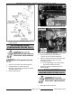
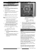
6. Remove POWER SUPPLY BOX.
7. On battery fryer sections only, remove splash
guard from base frame.
8. Remove gas manifold and frame assembly from
the fryer<s base frame:
A. Remove gas burners as necessary.
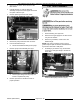
B. For the fryer sections above the filter
drawer assembly on battery fryers or single
floor model fryers, remove mounting nuts
securing gas manifold and frame assembly
to the fryer’s base frame.
C. For all other fryer sections in a battery only,
remove mounting nuts securing gas
manifold and frame assembly to the V
shaped frame support bracket.
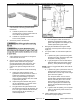
9. Disconnect swivel fitting from fry tank at the rear
(shortening line inlet to fry tank).
10. Disconnect flexible gas line fitting at manual
shutoff valve (gas supply inlet to valve).
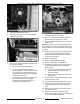
11. Remove screws securing the top of fry tank to
the flue wrap.
NOTE: Remove wire ties securing lead wires and
wiring harnesses as necessary before removing fry
tank; and when removing components from fry tank
for reuse.
12. Grasp the fry tank at the top (by flue) and front
lip, then lift fry tank assembly from the fryer
body. Place the assembly on floor or table for
removal of components.
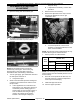
13. Remove GAS PILOT.
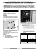
14. Remove TEMPERATURE PROBE.
15. Remove HIGH LIMIT THERMOSTAT.
16. On battery fryer sections only, when removing
fry tank from sections with the mechanical
discard valve:
A. Loosen u-bolt securing discard pipe with
male quick disconnect fitting to the
mounting bracket.
B. Remove pipe from elbow on mechanical
discard valve.
17. Remove bolts securing gas manifold and frame
assembly to the fry tank.
18. Pull the gas manifold assembly from fry tank.
19. Disconnect drain valve interlock switch (DVI)
connector (2 pin) and remove manual drain
valve.
20. Remove screws securing flue box to fry tank
then remove flue box.
21. Reverse procedure to install all the parts
removed from original fry tank onto replacement
fry tank, then install the assembly.
F25377 (March 2010)Page 13 of 36