
Fryer User Manual


GRA SERIES GAS FRYERS - REMOVAL AND REPLACEMENT OF PARTS
4. Remove screws securing the high limit to
mounting bracket.
5. Remove the capillary tube retaining and packing
nuts.
6. Remove screws securing mounting clips and
capillary tube to the fryer heat tube (inside tank)
then remove capillary tube.
7. Reverse procedure to install.
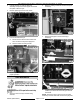
POWER SUPPLY BOX
COMPONENTS
NOTE: The power supply box must be removed to
access the following components: Ignition control
module, transformer, R1 pump motor relay, R2 fill
relay.
1. Disconnect all wiring harness connectors and
power cords from power supply box.
2. From rear, remove screw securing power
supply box to mounting bracket.
NOTE: Power supply box is slotted at the front and
secured by a hanging bracket (loose fit).
3. Remove cover from power supply box.
4. Disconnect lead wires from the component
being replaced then remove from power supply
box.
F25377 (March 2010) Page 10 of 36