INSTALLATION & OPERATION MANUAL ELECTRIC COMBINATION OVEN MODELS CEM6U ML-138076 CEM10U ML-138077 CEM20U ML-138078 For additional information on Vulcan-Hart or to locate an authorized parts and service provider in your area, visit our website at www.vulcanequipment.com VULCAN-HART DIVISION OF ITW FOOD EQUIPMENT GROUP, LLC WWW.VULCANEQUIPMENT.COM 3600 NORTH POINT BLVD.
ELECTRIC COMBI OVEN —2—
ELECTRIC COMBI OVEN TABLE OF CONTENTS INSTALLATION, OPERATION AND CARE OF ELECTRIC COMBI OVEN .................................. 5 GENERAL ................................................................................................................................... 5 UNPACKING ............................................................................................................................... 5 INSTALLATION .....................................................................................
ELECTRIC COMBI OVEN TABLE OF CONTENTS (CONTINUED) Fan Speed Selector .......................................................................................................... 16 Product Probe Temperature Selector Knob .................................................................... 17 Internal Product Temperature Probe Button ................................................................... 17 COOKING ...................................................................................................
ELECTRIC COMBI OVEN INSTALLATION, OPERATION AND CARE OF ELECTRIC COMBI OVEN INSTALLATION SAVE THESE INSTRUCTIONS FOR FUTURE USE Before installing, verify that the electrical supply agrees with the specifications on the data plate located on the lower front corner of the right side panel. If the supply and equipment requirements do not agree, do not proceed with the installation. Contact your dealer or Vulcan-Hart immediately.
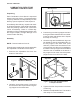
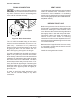
ELECTRIC COMBI OVEN COMBINATION OVEN STAND ASSEMBLY INSTRUCTIONS Allen Cap Screw Unpacking Each Combination Oven Stand is inspected before leaving the factory. The transportation company assumes full responsibility for safe delivery upon acceptance of the shipment. Immediately after delivery unpack and check for shipping damage. If the stand is damaged, save the packing material and contact the carrier immediately.
ELECTRIC COMBI OVEN 7. Install tray support (if supplied) after oven is installed onto stand. Use the four knurled screws to secure the support to the legs. LOCATION Allow space for operating the oven. Do not obstruct the ventilation port above the oven. To provide ventilation access, allow 1" of clearance on the left side of the oven and 21/2" clearance on the rear side of the oven. A minimum of 18" must be provided on the right side of the oven for operation, cleaning and service.
ELECTRIC COMBI OVEN POWER SUPPLY Plumbing connections must comply with applicable sanitary, safety and plumbing codes. Connect the power supply as follows: Electrical and grounding connections must comply with applicable portions of the National Electrical Code and/or other local electrical codes. WATER REQUIREMENTS Proper water quality can improve the taste of the food prepared in the oven, reduce liming in the oven cavity and extend equipment life.
ELECTRIC COMBI OVEN If the water supply fails to meet these standards, it will be necessary to install a water treatment system. A water filter system is required for the water supply line going to the treated water inlet of your Combi Oven. Follow the recommendations for use and installation instructions shipped with the water filter. If a water filter is not installed, the Combi Oven warranty is limited.
ELECTRIC COMBI OVEN DRAIN CONNECTION VENT HOOD In order to avoid any backpressure in the oven, do not make a solid connection to any drain. Failure to do so can damage the oven and will void the warranty. Local codes may require the oven to be located under an exhaust hood. Information on the construction and installation of ventilating hoods may be obtained from Vapor Removal from Cooking Equipment, NFPA Standard No. 96 (latest edition).
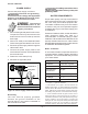
ELECTRIC COMBI OVEN OPERATION The oven and its parts are hot. Use care when operating, cleaning or servicing the oven. The cooking compartment contains live steam. Stay clear while opening the door. 1 6 2 7 3 8 4 OPERATING CONTROLS LOCATION 5 The Control Panel consists of the following controls, which are explained in the OPERATING CONTROLS FUNCTION section of this manual: 1. Oven Vent Valve 2. Oven Convection fan 3. Cooking Selector Knob 4. Warming - Rethermalization 5. Combination Cooking 6.
ELECTRIC COMBI OVEN Oven Vent Valve Cooking Selector Knob The Oven Vent Valve opens or closes the Vent to adjust the amount of steam venting from the oven. Pull the Oven Vent Valve out to open it. Push it in to close it. The Cooking Selector Knob has seven selectable positions corresponding to the different cooking modes of the oven, or the off position as shown.
ELECTRIC COMBI OVEN Warming - Rethermalization Mode Use the rethermalization mode to warm-up (rethermalize) refrigerated foods. Warming is accomplished in the combined mode at a temperature range of 210°F (100°C) to 518°F (270°C) on low speed. Foods cook quickly and brown evenly while keeping the product moist and flavorful. The Oven Timer Adjustment Knob must be set to continuous, or a specific time must be set, and the door must be closed in order for the Oven Convection Fan to operate.
ELECTRIC COMBI OVEN Steam Cooking The main advantage of steaming is the nutritional values are maintained. It is the most efficient means of cooking and the food does not lose its moisture. Steaming is conducted at 212°F (100°C). In the steam mode the convection fan does not start until the oven reaches 176°F (80°C). Adjustment Knob must be set to continuous, or a specific time must be set, and the door must be closed in order for the Oven Convection fan to operate.
ELECTRIC COMBI OVEN Oven Temperature Button Oven Timer Button During a cooking cycle, press the Oven Temperature Button to display current oven temperature. The Oven Timer button is used to change the timer display and to silence the audible end of the cook cycle alarm. During cooking, the timer displays the remaining time. Pushing the Oven Timer button toggles the display to the oven set time.
ELECTRIC COMBI OVEN Humidity Control Oven Light Button The Humidity Control button controls the level of moisture in the oven. This is essential for cooking products with low moisture content such as bread, biscuits, cakes and soft items. The Humidity Control button is also used to prevent roasts from burning or losing their moisture. The Humidity Control button has two positions.
ELECTRIC COMBI OVEN Internal Product Probe Temperature Selector Knob Internal Product Temperature Probe Button The optional Internal Product Probe that can be attached to maintain specific internal cooking temperatures. The temperature range is from 68°F (20°C) to 210°F (99°C). For such items as roast-beef, pâté, etc., the internal cooking temperature is important to maintain. By using the Internal Product Probe, the oven will switch off when the desired internal cooking temperature is reached.
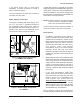
ELECTRIC COMBI OVEN COOKING Make sure the hinged back of the oven cavity is completely closed and the thumb screws are secured properly. To start up oven: 2. Place the product with probe in place, in or near the center of the oven. 3. Remove the protective cap and insert the probe electrical connector into the probe connection on the oven as shown below (Figure 28). 1. Select the desired cooking mode. 2. Select the desired cooking time by turning the selector knob clockwise to the desired time.
ELECTRIC COMBI OVEN DISPLAYING AND MODIFYING COOKING SETTINGS If the Internal Product Temperature Probe is hot at the start of the cooking cycle due to oven pre-heating, the display will flash until the actual temperature of the food is displayed and then cooking will commence. Cook and Hold Cook and Hold is only available when using the Internal Product Temperature Probe. At the end of the cooking cycle, the product is kept warm without its temperature falling below 158°F (70°C).
ELECTRIC COMBI OVEN Change Cooking Settings DAILY SHUTDOWN To change either the set temperature, timer or internal temperature while cooking: 1. Place the Selector Knob to 0 (OFF). 1. Press the relevant button and the LED will illuminate. 3. Leave door open. 2. Clean the oven interior. 2. Turn the knob. EXTENDED SHUTDOWN After a few seconds, the new parameter will be accepted and the LED will extinguish. 1. Perform DAILY SHUTDOWN procedure. 2. Turn off the circuit breakers.
ELECTRIC COMBI OVEN Safe Cooking Temperatures After desired cooking temperature is reached, remove meat from heat source and let stand 10 to 15 minutes before carving. The amount of time required for resting varies with the size of the cut of your meat. During this resting time, the meat continues to cook (meat temperature will rise 5 to 20 degrees after it is removed from the heat source) and the juices redistribute.
ELECTRIC COMBI OVEN CLEANING NOTE: Do not use any cleaners (soaps, detergents, disinfectants) that contain chlorine or chlorides. OVEN DRAINS Weekly 1. Thoroughly clean the exposed surfaces (sides, front, door and top) with a damp cloth. 2. Polish with a clean cloth. 3. To remove discolorations, use a nonabrasive cleaner. To keep the oven drain free of blockage: 1. Inspect the oven drain daily for any blockage. 2. Remove any particles or debris from the perforated strainer daily (more often if needed).
ELECTRIC COMBI OVEN STAINLESS STEEL EQUIPMENT CARE AND CLEANING steel. Other deposits from food preparation and service must be properly removed. Contrary to popular belief, stainless steels ARE susceptible to rusting. Chlorides are found nearly everywhere. They are in water, food and table salt. One of the worst chloride perpetrators can come from household and industrial cleaners. Corrosion on metals is everywhere. It is recognized quickly on iron and steel as unsightly yellow/orange rust.
ELECTRIC COMBI OVEN 5. Keep your food equipment clean. immediately. The sooner you wipe off standing water, especially when it contains cleaning agents, the better. After wiping equipment down, allow it to air dry; oxygen helps maintain the stainless steel’s passivity film. Use alkaline, alkaline chlorinated or nonchloride cleaners at recommended strength. Clean frequently to avoid build-up of hard, stubborn stains.
ELECTRIC COMBI OVEN MAINTENANCE The oven and its parts are hot. Use care when operating, cleaning or servicing the oven. The cooking compartment contains live steam. Stay clear while opening the door. Do not touch new bulb glass with A water treatment system is recommended for the combination oven. Refer to the supplier’s manual for normal maintenance procedures for proper scale-free operation. The oven cavity should be delimed when symptoms occur (see Troubleshooting Chart).
ELECTRIC COMBI OVEN MESSAGES AND ALARMS Messages When applicable, the Oven Timer LED will display the following messages: LCD DISPLAY MESSAGE DESCRIPTION door The oven door is open, or the door drip tray is not in place or is missing. Cont The Selector Knob has been rotated counterclockwise and the oven has been placed in continuous operation mode. HoLd (Flashing) Cook cycle is complete and oven is entering the Cook and Hold mode. HoLd (Steady) The oven is in Cook and Hold mode.
ELECTRIC COMBI OVEN TROUBLESHOOTING Problem Oven not heating/steaming Possible Cause / Suggested Corrective Action No main power source / Check power source or circuit breaker. Cooking Selector Knob in 0 position / Turn Selector Knob to the desired cooking operation. Door is open / Close the door. Oven door leaks Damaged door gasket / Check door gasket for damage. If adjustment or replacement is needed, contact your Authorized Vulcan-Hart service provider.
ELECTRIC COMBI OVEN SERVICE AND PARTS INFORMATION To obtain service and parts information, contact the Vulcan-Hart Service Agency in your area or refer to our website www.vulcanequipment.com for a complete listing of authorized service and parts providers. When calling for service the following information must be available: • Model Number • Serial Number • Manufacture Date (MD) • Voltage (09-10) — 28 — PRINTED IN U.S.A.