SERVICE MANUAL ELECTRIC COUNTER TOP TILTING KETTLES K6ETT ML-136067 K12ETT ML-136068 K20ETT ML-136069 K12ETT ON STAND This Manual is prepared for the use of trained Vulcan Service Technicians and should not be used by those not properly qualified. This manual is not intended to be all encompassing.
ELECTRIC COUNTER TOP TILTING KETTLES TABLE OF CONTENTS GENERAL . . . . . . . . . . . . . . . . . . . . . . . . . . . . . . . . . . . . . . . . . . . . . . . . . . . . . . . . . . . . . . . . . . . . . . . . . . . . . . . . Introduction . . . . . . . . . . . . . . . . . . . . . . . . . . . . . . . . . . . . . . . . . . . . . . . . . . . . . . . . . . . . . . . . . . . . . . . . . . . . Tools . . . . . . . . . . . . . . . . . . . . . . . . . . . . . . . . . . . . . . . . . . . . . . . . . . . . . . . . . . .
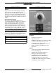
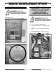
ELECTRIC COUNTER TOP TILTING KETTLES - GENERAL GENERAL INTRODUCTION CONTROL PANEL General The procedures in this manual apply to all models unless otherwise specified. The pictures and illustrations are of a model K6ETT countertop tilting kettle unless otherwise noted. All information and specifications contained in this manual are based on the latest product information available at the time of printing.
ELECTRIC COUNTER TOP TILTING KETTLES - GENERAL SPECIFICATIONS Reservoir Jacket Fluid • Water - Use only distilled water for partial re-filling of the jacket (purchase locally). • Dowfrost heat transfer fluid Part No. 558038 (5 gallon). Use during a complete re-fill of the jacket with new fluid. Refer to service procedures for volumes. Electric The kettle models listed in this manual, with exception of 480V steamers, are shipped pre-wired for 208/60/3 operation.
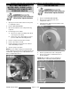
ELECTRIC COUNTER TOP TILTING KETTLES - REMOVAL AND REPLACEMENT OF PARTS REMOVAL AND REPLACEMENT OF PARTS COVERS AND PANELS ELECTRICAL PANEL COMPONENTS - WATER LEVEL CONTROL, TRANSFORMER, CONTACTORS AND TEMPERATURE CONTROL Control Box Cover 1. Remove CONTROL BOX COVER. 2. Disconnect lead wires from component being replaced. 3. Remove screws securing the component to panel. 4. Reverse procedure to install and check for proper operation.
ELECTRIC COUNTER TOP TILTING KETTLES - REMOVAL AND REPLACEMENT OF PARTS BOTTOM COMPONENTS WATER LEVEL PROBE (LLCO), TEMPERATURE SENSOR AND PRESSURE SWITCH POTENTIOMETER 1. Open pressure relief valve until reservoir jacket is completely vented. 2. Remove BOTTOM COVER. 3. Disconnect lead wires from component being replaced. 4. If removing pressure switch: A. Disconnect compression fitting from elbow near the pressure switch. B.
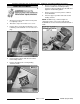
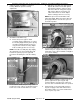
ELECTRIC COUNTER TOP TILTING KETTLES - REMOVAL AND REPLACEMENT OF PARTS HEATING ELEMENT 1. Open pressure relief valve until reservoir jacket is completely vented. 2. Tilt kettle to expose the heater access cover. 3. Remove three screws where indicated. Loosen remaining screw and allow cover to rotate out of way. 4. Note lead wire locations and disconnect wires from heating element. 5. Remove mounting bolts securing heating element to kettle. 6. Reverse procedure to install.
ELECTRIC COUNTER TOP TILTING KETTLES - REMOVAL AND REPLACEMENT OF PARTS KETTLE ASSEMBLY Removal 1. Place kettle in full upright position. 2. Support kettle using 2x4 blocks of wood. 3. Remove CONTROL BOX COVER. 4. Disconnect thermocouple lead wires from temperature control and the 4 pin wiring harness connector. 5. Note lead wire locations and disconnect from load side of contactors. 6. Remove wire tie securing lead wire bundle to control box. 7. Remove three set screws on pivot stop collar.
ELECTRIC COUNTER TOP TILTING KETTLES - REMOVAL AND REPLACEMENT OF PARTS 11. If re-installing kettle assembly, proceed to Installation in this section. If installing a replacement kettle assembly, remove components as outlined below from old kettle assembly for re-use. C. Remove kettle support and bearing housing assembly from support shaft. A. Open pressure relief valve until reservoir jacket is completely vented. B.
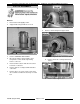
ELECTRIC COUNTER TOP TILTING KETTLES - REMOVAL AND REPLACEMENT OF PARTS 3. Square the kettle assembly to control box housing. Maintain squareness during adjustments. A. Slide pivot stop collar onto support shaft. Operate tilt lock then slide collar against inner bearing. Hold the collar in position and release tilt lock. Verify pivot stop pin fully engages with the slot in pivot stop collar for the tilt lock as shown. Adjust kettle assembly position as necessary.
ELECTRIC COUNTER TOP TILTING KETTLES - REMOVAL AND REPLACEMENT OF PARTS NOTE: Allow cleaner to fully evaporate before applying primer. Spay primer on the threads and allow to dry for 60 seconds. Shake Loctite 242 bottle thoroughly to mix then apply several drops of the threadlocker to threads. Do not allow the tip of bottle to touch a primed surface as it will activate the Loctite 242 in the bottle. 9. BEARINGS 1. Remove KETTLE ASSEMBLY (procedure includes outer bearing removal). 2.
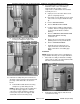
ELECTRIC COUNTER TOP TILTING KETTLES - REMOVAL AND REPLACEMENT OF PARTS SHAFT SEAL All Models 1. To access shaft seal between kettle and control box housing, remove KETTLE ASSEMBLY. 2. Remove shaft seal from control box housing. 3. Clean mounting surface on control box housing then install replacement shaft seal. 4. Install KETTLE ASSEMBLY. 3. Remove kettle support and bearing housing assembly from support shaft. 4. Remove shaft seal from kettle support. 5.
ELECTRIC COUNTER TOP TILTING KETTLES - REMOVAL AND REPLACEMENT OF PARTS 6. Reverse procedure to complete the installation and check for proper operation. K20ETT WITH SHAFT SEAL INSTALLED PIVOT STOP PIN 1. Remove CONTROL BOX COVER. 2. Remove retaining ring from pivot stop pin. 3. Reverse procedure to install. NOTE: When installing, apply Lubriplate 630-AA to mating surfaces on pivot stop pin.
ELECTRIC COUNTER TOP TILTING KETTLES - SERVICE PROCEDURES AND ADJUSTMENTS SERVICE PROCEDURES AND ADJUSTMENTS TEMPERATURE CONTROLLER TEST A. Verify heat light (amber) comes on and heating element is energized. B. If heat light does not remain on or flashes momentarily as temperature setting is slowly increased, verify condition of potentiometer as outlined under POTENTIOMETER TEST.
ELECTRIC COUNTER TOP TILTING KETTLES - SERVICE PROCEDURES AND ADJUSTMENTS POTENTIOMETER TEST THERMOCOUPLE TEST 1. Remove potentiometer from control panel as outlined in REMOVAL AND REPLACEMENT OF PARTS. 2. Turn potentiometer shaft fully counterclockwise to the lowest setting. 3. Set VOM to measure resistance. 4. Connect meter leads to the white and black lead wires on potentiometer terminals. A. 5. 1. Access the temperature controller as outlined in REMOVAL AND REPLACEMENT OF PARTS. 2.
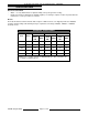
ELECTRIC COUNTER TOP TILTING KETTLES - SERVICE PROCEDURES AND ADJUSTMENTS HEATING ELEMENTS 1. Access heating element as outlined in REMOVAL AND REPLACEMENT OF PARTS. 2. Measure voltage at heating element terminals and verify it against the data plate voltage. A. 3. If voltage is incorrect, find the source of the problem. If voltage is correct, check current draw (amps) through the heating element lead wires. If current draw is correct then heating element is ok. See table below for proper values.
ELECTRIC COUNTER TOP TILTING KETTLES - SERVICE PROCEDURES AND ADJUSTMENTS VENTING NOTE: This procedure outlines venting the reservoir jacket to remove air for proper heat transfer to the kettle contents. FILLING THE RESERVOIR JACKET NOTE: The reservoir water level must be maintained high enough to submerge the heating element. If low water light comes on during use, the level may be below water level probe (LLCO) and must be replenished before heating can continue.
ELECTRIC COUNTER TOP TILTING KETTLES - SERVICE PROCEDURES AND ADJUSTMENTS Complete Draining and Refill NOTE: Appearance of fluid will no longer be clear after usage in kettle. 1. Turn power switch off and set temperature dial to lowest setting. 2. Open pressure relief valve until reservoir jacket is completely vented. 3. Remove bottom cover as outlined under COVERS AND PANELS. 4. Remove water level probe (LLCO) from kettle as outlined in REMOVAL AND REPLACEMENT OF PARTS. 5.
ELECTRIC COUNTER TOP TILTING KETTLES - ELECTRICAL OPERATION ELECTRICAL OPERATION COMPONENT FUNCTION Water Level Control (WLC LLCO) . . . . . . . . . . Low water level control. Monitors condition of the WLC LLCO water level probe. Protects kettle from a low water condition in the reservoir jacket and removes power from heating circuit when kettle is tilted. Probe, Water Level (LLCO) . . . . . . . . . . . . . . Low Level Cut-Off (LLCO) probe connected to WLC (LLCO). Controls power to heating circuit.
ELECTRIC COUNTER TOP TILTING KETTLES - ELECTRICAL OPERATION COMPONENT LOCATION F35496 (August 2009) Page 20 of 28
ELECTRIC COUNTER TOP TILTING KETTLES - ELECTRICAL OPERATION Page 21 of 28 F35496 (August 2009)
ELECTRIC COUNTER TOP TILTING KETTLES - ELECTRICAL OPERATION WATER LEVEL CONTROL (WLC LLCO) The water level control provides low level cut-off protection to shut off the heat source in case the fluid level in the kettle reservoir jacket drops below the WLC LLCO probe. A single low level cut-off probe (LLCO) is connected to the control. The water level control has input voltage of 120VAC across terminals L1 and L2 which powers the primary side of the transformer on the board.
ELECTRIC COUNTER TOP TILTING KETTLES - ELECTRICAL OPERATION SEQUENCE OF OPERATION 1. Conditions. A. Kettle connected to correct voltage supply and is properly grounded. 1) B. Power switch and light (1LT) (amber) are off. C. Low water light (2LT) (red) is off. D. Pressure switch (1PAS) contacts closed. E. Temperature dial at lowest setting (potentiometer fully CCW). 1) F. 2. 3. Kettle at room temperature and in the full upright position. A. Power light (1LT) (amber) comes on. B.
ELECTRIC COUNTER TOP TILTING KETTLES - ELECTRICAL OPERATION SCHEMATIC DIAGRAM F35496 (August 2009) Page 24 of 28
ELECTRIC COUNTER TOP TILTING KETTLES - ELECTRICAL OPERATION WIRING DIAGRAMS Heating Element Wiring Page 25 of 28 F35496 (August 2009)
ELECTRIC COUNTER TOP TILTING KETTLES - ELECTRICAL OPERATION F35496 (August 2009) Page 26 of 28
ELECTRIC COUNTER TOP TILTING KETTLES - TROUBLESHOOTING TROUBLESHOOTING SYMPTOM POSSIBLE CAUSES Kettle does not heat, power light is lit, heat light is lit, low water light is not lit. 1. Limiting contactor (1CON) malfunction. 2. Regulating contactor (2CON) malfunction. 3. Heating element malfunction. Kettle does not heat, power light is lit, low water light is lit, heat light is not lit. 1. Fluid level in reservoir jacket below water level probe (LLCO). 2.
ELECTRIC COUNTER TOP TILTING KETTLES F35496 (August 2009) Printed in U.S.A.