
Hot Beverage Maker User Manual
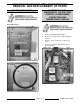

ELECTRIC COUNTER TOP TILTING KETTLES
TABLE OF CONTENTS
GENERAL ................................................................................ 3
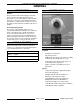
Introduction ............................................................................ 3
Tools................................................................................. 3
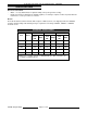
Specifications .......................................................................... 4
REMOVAL AND REPLACEMENT OF PARTS .................................................... 5
Covers and Panels ..................................................................... 5
Electrical Panel Components - Water Level Control, Transformer, Contactors and Temperature Control . . . 5
Bottom Components - Water Level Probe (LLCO), Temperature Sensor and Pressure Switch ........... 6
Potentiometer .......................................................................... 6
Heating Element........................................................................7
Kettle Assembly ........................................................................ 8
Bearings ............................................................................. 11
Shaft Seal............................................................................12
Pivot Stop Pin.........................................................................13
SERVICE PROCEDURES AND ADJUSTMENTS................................................. 14
Temperature Controller Test ............................................................. 14
Potentiometer Test ..................................................................... 15
Thermocouple Test ..................................................................... 15
Heating Elements ...................................................................... 16
Venting .............................................................................. 17
Filling the Reservoir Jacket .............................................................. 17
ELECTRICAL OPERATION..................................................................19
Component Function ................................................................... 19
Component Location ................................................................... 20
Water Level Control (WLC LLCO) .........................................................22
Sequence of Operation .................................................................. 23
Schematic Diagram .................................................................... 24
Wiring Diagrams ....................................................................... 25
TROUBLESHOOTING ...................................................................... 27
© VULCAN 2009
F35496 (August 2009)
Page 2 of 28