
Fryer User Manual
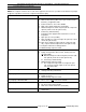

ER SERIES FRYER SERVICE MANUAL SUPPLEMENT - TROUBLESHOOTING
F24696 (May 2001) Page 52 of 56
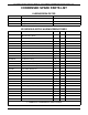
COMPUTER CONTROL
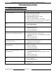
HARNESS PIN-OUTS CHART
NOTE
:
The terms right and left throughout the table below have the following meanings: Right equals Full vat or right
side split vat; Left equals left side, split vat only.
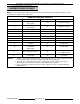
COMPUTER CONTROL PIN-OUTS
PIN # DESCRIPTION PIN # DESCRIPTION
1
Right power
input "status"
13
2
24 VAC input ground
2
Left power
input "status"
14 Right basket output
3
1
Right input 15 Right heat output
4
1
Left input 16 Left heat output
5
1
Right input 17
1
24 VAC main input
6
1
Left input 18 no connection
7 no connection 19 Left basket output
8 no connection 20 no connection
9
2
ground 21 no connection
10
Drain valve switch(es)
(if installed)
input "status"
22 no connection
11
1,
3
Door switch input "status" 23
Computer power input
(+) 12 VDC nominal
12
1,
2
Full vat or Split vat
mode Input
24
Computer power input
(-) 12 VDC
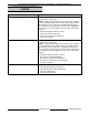
NOTES
:
1. 24VAC - control system main input to pin 17; jumpered to pins 3, 4, 5, 6, 11 & 12 (split vat only). Input
to jumpered pins must be present or computer control will not function properly.
2. 24VAC ground - control system input to pin 13; jumpered to pins 9 & 12 (full vat only). Input to
jumpered pins must be present or computer control will not function properly.
3. Pin 11 - door switch no longer used on these models. Input must remain or computer will display
"DOOR OPEN".