
User Guide

ELECTRIC COUNTER TOP TILTING KETTLES - REMOVAL AND REPLACEMENT OF PARTS
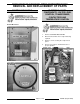
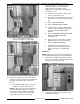
3. Square the kettle assembly to control box
housing. Maintain squareness during
adjustments.
4. On K6ETT and K12ETT only.
A. Ensure the pour stop pin on kettle
assembly engages with tilt stop on control
box housing. Approximately 3/16" spacing
should be maintained between the pour
stop pin and control box housing. Adjust
kettle assembly position as necessary.
NOTE: The kettle assembly may drop slightly
after 2x4 blocks are removed and when fully
loaded. The spacing of pour stop pin will
prevent it from rubbing the control box during
tilt.
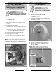
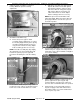
5. Insert lead wire bundle thru pivot stop collar.
Position pivot stop collar as shown in the picture
below. Set screws should remain out of collar.
A. Slide pivot stop collar onto support shaft.
Operate tilt lock then slide collar against
inner bearing. Hold the collar in position
and release tilt lock. Verify pivot stop pin
fully engages with the slot in pivot stop
collar for the tilt lock as shown. Adjust
kettle assembly position as necessary.
NOTE: The pin location shown will lock the
kettle fully upright. When the kettle is tilted, the
pin engages with the slot near the top to lock
the kettle in position.
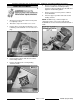
6. Insert lead wire bundle thru the outer bearing.
Slide bearing onto support shaft and position it
against pivot stop collar. Install bolts and tighten
to secure the bearing.
7. Apply Lubriplate 630-AA to mating surfaces on
pivot stop pin. Ensure pivot stop pin fully
engages with the slot in pivot stop collar and
does not catch or bind when tilt lock is operated.
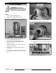
8. Clean threads (screw & hole) with cleaner &
degreaser. Apply Loctite 7471 Primer N and
Threadlocker 242 to set screws and threaded
holes on pivot stop collar.
F35496 (August 2009) Page 10 of 28