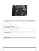
SERVICE MANUAL GAS RESTAURANT RANGE MG 12, 24, 36, 48 AND 60 MODEL MG12 MG24 MG36 MG48 MG60 ML-52549 ML-52514 ML-52522 ML-52523 ML-52524 MG12 VULCAN-HART COMPANY, FORM 30837 Rev. A (7-95) P.O. BOX 696, LOUISVILLE, KY 40201-0696, TEL.
IMPORTANT FOR YOUR SAFETY THIS MANUAL HAS BEEN PREPARED FOR PERSONNEL QUALIFIED TO INSTALL GAS EQUIPMENT, WHO SHOULD PERFORM THE INITIAL FIELD START-UP AND ADJUSTMENTS OF THE EQUIPMENT COVERED BY THIS MANUAL. POST IN A PROMINENT LOCATION THE INSTRUCTIONS TO BE FOLLOWED IN THE EVENT THE SMELL OF GAS IS DETECTED. THIS INFORMATION CAN BE OBTAINED FROM THE LOCAL GAS SUPPLIER.
TABLE OF CONTENTS MG SERIES GAS RESTAURANT MODULAR RANGE MODELS . . . . . . . . . . . . . . . . . . . . . . . . . . . . . . . . . . 4 SERVICE NOTATIONS . . . . . . . . . . . . . . . . . . . . . . . . . . . . . . . . . . . . . . . . . . . . . . . . . . . . . . . . . . . . . . . . . . . . 5 SERVICE .............................................................................. 5 CHECKS AND ADJUSTMENTS . . . . . . . . . . . . . . . . . . . . . . . . . . . . . . . . . . . . . . . . . . . . . . . . . . . . .
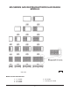
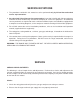
MG SERIES GAS RESTAURANT MODULAR RANGE MODELS PL-40044-1 MODEL SUFFIX DESIGNATIONS S - 12" Griddle F - 24" Griddle X - 36" Griddle Z - 48" Griddle T - Thermostatic Control –4–
SERVICE NOTATIONS 1. The procedures outlined in this manual are to be performed only by Vulcan-Hart authorized service representatives. 2. An authorized Vulcan-Hart service representative is one who is familiar with Vulcan equipment and who has been endorsed by Vulcan-Hart Company to service the equipment.
Adjustments 1. Legs Tools Required: Carpenter's level, channel locks. If the cooked product seems to be lopsided, check the leveling of the modular range. Place a carpenter's level across the range top and level the range from front to back and from side to side. To adjust the leveling of the range, tilt the range to one side, and using channel locks, unscrew the adjustable leg insert as required. Repeat this procedure as necessary for each leg. 2.
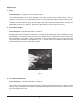
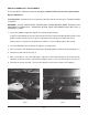
The gas/air balance is controlled by an air shutter on the front of the top burner. A yellow streaming flame on the burner is an indication of insufficient air. To correct this condition, loosen the screw locking the shutter into position. Rotate the air shutter open until the burner flame begins to lift from the burner, then close the shutter slightly down again and lock it into place (Fig's. 2 & 3). Fig. 2 Fig.
PILOT LIGHTING AND ADJUSTMENTS Although pilot lighting procedures are to be performed by both installation and operation personnel, only installation/service personnel should attempt to make any pilot or burner adjustments to this range. Operation personnel are authorized only to perform procedures for pilot lighting. All adjustment procedures associated with pilot lighting must be performed by an authorized Vulcan-Hart installation or service person.
Fig. 4 3. If pilot fails to light, turn main gas supply OFF. Wait 5 minutes and repeat the above procedures. 4. Turn one open top burner valve ON to remove air from the gas line. Turn burner OFF when gas begins to flow. Open Top Burner Adjustments Tools Required: Standard flat blade screwdriver. 1. After pilot is lit, turn open top burners ON. 2. Adjust burner flame, if necessary, by rotating the adjustment screw of the pilot valve located on the manifold pipe (see Fig. 1).
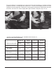
GRIDDLE THERMOSTAT ADJUSTMENTS These procedures should be performed only by a qualified Vulcan-Hart service representative. Bypass Adjustment Tools Required: Thermometer test instrument (not of bi-metal or mercury type), standard flat blade screwdriver. WARNING: DO NOT USE BI-METAL OR MERCURY THERMOMETERS WHEN TESTING FOOD EQUIPMENT OR PRODUCTS. CHEMICALS WITHIN THESE INSTRUMENTS MAY BE TOXIC IF EXPOSED TO FOOD. 1. Check the griddle temperature against the thermostat dial setting.
Temperature Calibration Tools Required: Thermometer test instrument (not of bi-metal or mercury type), standard flat blade screwdriver. WARNING: DO NOT USE BI-METAL OR MERCURY THERMOMETERS WHEN TESTING FOOD EQUIPMENT OR PRODUCTS. CHEMICALS WITHIN THESE INSTRUMENTS MAY BE TOXIC IF EXPOSED TO FOOD. 1. Check the griddle temperature against the thermostat dial setting. Place thermocouple in center of each individual griddle section. Each griddle section must be tested. 2.
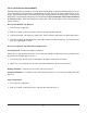
8. To recalibrate, hold the thermostat dial in place. Insert screwdriver into dial shaft to engage the calibration stem adjustment screw (Fig. 8). Push inward (do not turn stem). 9. While holding stem calibration screw in place, turn thermostat dial until it is set on the actual temperature shown by the testing device. 10. Release the calibration screw and reinstall the dial insert. 11. Set the dial to 450°F and recheck temperature reading every 5 minutes over a 15-minute period.
A leak limiter is supplied with every regulator to limit gas leakage if regulator rupture occurs. Do not obstruct leak limiter on gas pressure regulator as obstruction may cause regulator to malfunction. Tools Required: Manometer, flat blade screwdriver, 6" adjustable wrench, slip joint plier or pipe wrench. 1. Connect the manometer to the pressure tap provided on the manifold pipe near the regulator (Fig. 9). Fig. 9 2. With only two open top burners ON, note the manometer reading.
Fig. 10 Fig. 11 Check also for gas leak at vent. If vent is leaking gas, replace the regulator. REGULATOR ADJUSTMENT Tools Required: Flat blade screwdriver, manometer, and 6" adjustable wrench. Before making a regulator adjustment, always verify that the incoming line pressure is correct. The required incoming minimum line pressure for the modular range series is 5.0" Water Column for natural gas and 11.0" Water Column for propane gas.
1. Connect the manometer to the pressure tap provided on the rear manifold pipe (see Fig. 9). 2. Check the reading. The reading should be 3.7" Water Column for natural gas and 10.0" Water Column for propane gas. 3. If reading is incorrect and the proper line pressure has been verified, then adjust the regulator. Using a standard flat blade screwdriver, remove the regulator adjustment cap (Fig's. 13 & 14). Fig. 13 Fig. 14 4.
GRIDDLE THERMOSTAT CHECKS AND CALIBRATION Refer to GRIDDLE THERMOSTAT ADJUSTMENTS in this manual for the procedures for checking and calibrating the thermostat for the griddle. GRIDDLE THERMOSTAT REPLACEMENT Tools Required: Pipe wrench, 6" adjustable wrench, 1⁄8" flat blade screwdriver, 5⁄16" socket, and socket wrench. 1. Disconnect range gas supply and allow range to cool. 2.
Fig. 16 Fig. 17 7. Unscrew the thermostat from the manifold pipe (Fig's. 18, 19, & 20). Fig. 18 Fig. 19 Fig.
8. Replace thermostat mounting block. Place pipe joint compound on the threaded end of the new thermostat mounting block to be installed onto the range. 9. Install the new thermostat by reversing Steps 1 through 7 above. Do not kink the new capillary line when installing new thermostat. Using a soap and water solution, test the thermostat for gas leak after installing.
3. Remove valve from range manifold. 4. With pipe thread sealant covering the threads, install new pilot valve by reversing Steps 1 through 3. TOP SECTION BURNER VALVE AND NOZZLE CHECK After a long period of use on the range, the top section burner valve can show signs of wear. Check valve for gas leakage and sloppy valve control. Check also for valve nozzle blockage or damage.
FORM 30837 Rev. A (7-95) – 20 – PRINTED IN U.S.A.