INSTALLATION & OPERATION MANUAL VEC SERIES ELECTRIC CONVEYOR OVENS MODELS VEC3018 10KW 15KW VEC4018 VEC3624 VEC3632 VEC4824 VEC4832 VEC6024 VEC6032 VULCAN-HART ML-126198 ML-126401 ML-126199 ML-114836 ML-114837 ML-114838 ML-114739 ML-114797 ML-114798 COMPANY, FORM 31062 (10-98) P.O. BOX 696, LOUISVILLE, KY 40201-0696, TEL.
TABLE OF CONTENTS GENERAL............................................................................................................................................. 3 INSTALLATION .................................................................................................................................... 3 Unpacking ................................................................................................................................. 3 Location ............................................
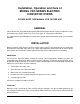
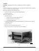
Installation, Operation and Care of MODEL VEC SERIES ELECTRIC CONVEYOR OVENS PLEASE KEEP THIS MANUAL FOR FUTURE USE GENERAL Vulcan-Hart ovens are produced with quality workmanship and material. Proper installation, usage, and maintenance of your oven will result in many years of satisfactory performance. It is suggested that you thoroughly read this entire manual and carefully follow all of the instructions provided.
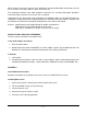
When installed, minimum clearance from combustible and non-combustible construction must be 2.5" (63.5 mm) at the sides and 2.5" (63.5 mm) at the rear. The installation location must allow adequate clearances for servicing and proper operation. A minimum front clearance of 36" (914.4 mm) is required. Information on the construction and installation of ventilating hoods may be obtained from the standard for "Vapor Removal from Cooking Equipment," NFPA No.
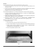
Installing Stacked Ovens 1. Stack ovens after basic oven is installed. 2. Lift top oven and place it on top of bottom oven. 3. No fasteners are required; the weight of the oven will keep it in place. LEVELING Casters for this oven are of the non-adjustable type. For best results oven should be installed on a level floor.
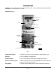
OPERATION WARNING: THE OVEN AND ITS PARTS ARE HOT. BE VERY CAREFUL WHEN OPERATING, CLEANING OR SERVICING THE OVEN. CONTROLS (Fig. 1) TEMPERATURE DISPLAY SET POINT INDICATOR LIGHT SET POINT SET POINT ARROWS TIME DISPLAY TIME RANGE SWITCH BELT SWITCH POWER SWITCH TIME KNOB DRIVE MOTOR FUSES CONTROL CIRCUIT FUSE PL-41123-1 Fig. 1 Temperature Display — Displays actual oven cavity temperature during cooking cycle. Set Point — Press to display set temperature.
Time Range Switch — Use to set cook time range from 2 to 8 minutes, 8 to 15 minutes, or 15 to 20 minutes. Switch must be on cook time range desired in order to change belt speed. Belt Switch — Push switch to ON to start conveyor belt; push to OFF to stop conveyor belt. Power Switch — Press ON to start oven; press OFF to stop oven. Time Knob — After Time Range Switch has been set to the desired time range, turn knob until desired time is reached on the display.
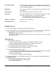
A baffle (Fig. 2) is located on each end of the oven. It can be adjusted higher or lower to accommodate the height of the product being cooked. To raise or lower baffles: 1. Loosen the two thumb screws (Fig. 2) - use insulated gloves. 2. Readjust baffle height. 3. Retighten the two thumb screws. BAFFLE THUMB SCREWS PL-41126-1 Fig. 2 Loading and Unloading the Oven 1. Place product in utensils (if required). 2. Set utensils or products on the entrance end of the belt; not in the oven tunnel. 3.
CLEANING WARNING: DISCONNECT ELECTRICAL POWER SUPPLY BEFORE CLEANING. Daily Clean the outside of the oven daily by wiping with a clean damp cloth. Avoid using abrasive powders or pads; these cleaners may damage the finish. Clean right-hand and left-hand crumb trays (Fig. 3). 1. Remove and wash in a sink as you would any normal utensil. 2. Replace crumb trays. Clean center crumb tray (Fig. 3). 1. Remove front panel. a. Grasp each side of the door handle and lift up. b.
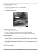
Conveyor To maintain proper belt tension, adjust the conveyor belt to remove any slack. 1. Locate the two adjustment screws (Fig. 4) on the right hand end (facing machine) of the conveyor assembly. 2. Loosen the nuts on the inside of the conveyor rack and turn the adjusting screws clockwise to increase belt tension. Be sure to adjust both screws an equal amount. 3. Retighten the nuts on the inside of the conveyor rack.
2. Conveyor Assembly Removal a. Remove conveyor crumb trays (see Fig. 3). b. Remove cover where conveyor shaft enters the left-hand control box (Fig. 5). REMOVE COVER PL-41129-1 Fig. 5 c. Lift up the drive end of the conveyor assembly and slide the conveyor assembly into the oven tunnel to remove the tension on the drive chain. d. Slip drive chain off the conveyor drive sprocket (Fig. 6). PL-41130 Fig.
e. Pull the entire conveyor assembly from the oven (Fig. 7). PL-41131 Fig. 7 f. Take conveyor assembly to cleaning area. g. Reverse this procedure to replace conveyor assembly. Weekly CAUTION: Intake fans and slots on the back of the oven and control box must be cleaned weekly. Any obstructions may cause motor damage. Use a long bristle brush to clean these areas. Clean the wire belt and frame with a stiff bristle brush as needed.
CONVEYOR BELT ASSEMBLING AND DISASSEMBLING (Fig. 8) Install the conveyor belt so that it always runs in the direction indicated by this arrow — the closed end of the loop toward the direction of travel. 1 The arrows in the belt illustrate the movement of the splicing strand between steps. When bending the splicing strand, try to limit bending to straight portions of the strand rather than in the "Z" bend area. 2 3 4 Splice one side completely before starting the other side.
COOKING CHART The times and temperatures shown in this chart are only suggestions. Experiment with your food products to determine the cooking temperatures and times that give you the best results. APPROX. TIME (IN MIN.) TEMP. (°F) / (°C) TYPE OF FOOD PRODUCT ITALIAN Pizza (par baked dough) Pizza (fresh dough) Pizza (thick pan type) Calzone (fresh dough) Pastas (precooked to gratin) 4 to 4.5 5.5 to 6.5 7.5 to 8.
MAINTENANCE WARNING: THE OVEN AND ITS PARTS ARE HOT. BE VERY CAREFUL WHEN OPERATING, CLEANING OR SERVICING THE OVEN. WARNING: DISCONNECT ELECTRICAL POWER SUPPLY BEFORE PERFORMING ANY MAINTENANCE ON THE OVEN. INSPECTION The oven should be inspected at least annually by a Vulcan-Hart authorized servicer. More frequent cleaning may be required due to oven grease vapors, dust, etc. It is imperative that control compartments and circulating air passageways of the oven be kept clean.
TROUBLESHOOTING GUIDE PROBLEM Power switch is on, but oven will not operate. POSSIBLE CAUSES • Blown fuse. • Problem with power supply. • Problem with power switch. ACTION • Replace fuse. • Contact your Vulcan-Hart servicer. • Contact your Vulcan-Hart servicer. Speed control shows "OL". • Conveyor belt is stuck. • Problem with belt motor. • Check the belt. • Contact your Vulcan-Hart servicer. Conveyor belt does not turn. • Problem with speed control. • Gear loose.