SERVICE MANUAL VSX BOILER BASE SERIES CONVECTION STEAMERS (GAS, ELECTRIC, DIRECT AND REGENERATED) VSX24G ML-52163 VSX24D ML-52827 VSX36G ML-52360 VSX36D ML-52830 VSX42GT ML-52376 VSX42DT ML-52834 VSX24E ML-52164 VSX36R ML-52831 VSX36E ML-52829 VSX42RT ML-52835 VSX42ET ML-52833 VSX24G SHOWN - NOTICE This Manual is prepared for the use of trained Vulcan Service Technicians and should not be used by those not properly qualified.
VSX SERIES STEAMERS TABLE OF CONTENTS GENERAL . . . . . . . . . . . . . . . . . . . . . . . . . . . . . . . . . . . . . . . . . . . . . . . . . . . . . . . . . . . . . . . . . . . . . . . . . . . . . Introduction . . . . . . . . . . . . . . . . . . . . . . . . . . . . . . . . . . . . . . . . . . . . . . . . . . . . . . . . . . . . . . . . . . . . . . . . Compartment Pan Capacity . . . . . . . . . . . . . . . . . . . . . . . . . . . . . . . . . . . . . . . . . . . . . . . . . . . . . . . .
VSX SERIES STEAMERS ELECTRICAL OPERATION . . . . . . . . . . . . . . . . . . . . . . . . . . . . . . . . . . . . . . . . . . . . . . . . . . . . . . . . . . . . . . Water Level Controls . . . . . . . . . . . . . . . . . . . . . . . . . . . . . . . . . . . . . . . . . . . . . . . . . . . . . . . . . . . . . . . . Solid State Low level Cut-Off & Differential Control . . . . . . . . . . . . . . . . . . . . . . . . . . . . . . . . . . . . . . . . . .
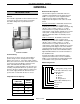
VSX SERIES STEAMERS - GENERAL GENERAL Boiler Code Descriptions INTRODUCTION General This manual is applicable for all models listed on the cover page. A convection steamer on a 42 inch base with a tilting kettle is pictured below for reference. Vulcan-Hart incorporates redundant controls in compliance with California Code (Cal-Code) and CSD-1 as an option on steam equipment when required by state and/or local building code requirements. Descriptions of the codes are listed below.
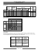
VSX SERIES STEAMERS - GENERAL SPECIFICATIONS Gas Steamers LINE PRESSURE MANIFOLD PRESSURE INPUT (BTU/HR) (INCHES W.C.) AMPS (INCHES W.C.) NATURAL LOAD PROPANE (WATTS) MAX MODEL VSX24G NAT. PROP. NAT. PROP. RECOMMEND MIN RECOMMEND (MAX) 120V MIN 200,000 200,000 4.0 10.0 7.0 5.0 11.0 11.0 200,000 200,000 4.0 10.0 7.0 5.0 11.0 11.0 240,000 240,000 4.0 10.0 7.0 5.0 11.0 11.0 200,000 200,000 4.0 10.0 7.0 5.0 11.0 11.0 240,000 240,000 4.0 10.0 7.0 5.0 11.
VSX SERIES STEAMERS - OPERATION Water Supply WATER CONDITIONING Supply pressure should be In line strainer for supply line Supply connection Total dissolved solids (TDS)* Total alkalinity Silica Chloride PH factor (*17.1 ppm = 1 grain of 20-80 psig (Not Supplied) cold less than 60 ppm less than 20 ppm less than 13 ppm less than 30 ppm 7 to 8 hardness) TOOLS This causes several problems: Standard 1. Reduce the heat transfer efficiency of the heating system.
VSX SERIES STEAMERS - OPERATION STEAMER OPERATION WARNING: THE STEAMER AND ITS PARTS ARE HOT. USE CARE WHEN OPERATING, CLEANING OR SERVICING THE STEAMER. THE COOKING COMPARTMENT CONTAINS LIVE STEAM. STAY CLEAR WHEN OPENING EACH DOOR. B. CABINET BASE BOILERS Ensure that all utility connections to the steamer have been made and are turned on.
VSX SERIES STEAMERS - OPERATION Electrically Powered Steam Boiler Open the cabinet door and turn main power switch ON. The red light will illuminate, water will begin filling the boiler and the blowdown solenoid valve will close. The boiler should fill, in 4 to11 minutes. Observe water level gauge glass to verify that water is in boiler and that the level in the gauge glass is about half full. Both valves on gauge glass assembly must be open to fill the gauge.
VSX SERIES STEAMERS - OPERATION COOKING COMPARTMENT CONTROLS When the steam pressure in the cooking compartment manifold reaches approximately 3 psi, the cooking compartment pressure switch closes, suppling power to the other controls. The ready lights will illuminate and after approximately one minute, the steam pressure in the boiler will reach the upper limit of 10 psi. If the pressure drops below approximately 3 psi, the pressure switch will open, removing power from the cooking compartment controls.
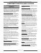
VSX SERIES STEAMERS - COMPONENT FUNCTION AND LOCATION COMPONENT FUNCTION AND LOCATION CABINET BASE BOILER CONTROLS Cycling Pressure Switch - controls boiler pressure between prescribed limits by turning the heat source on and off. WARNING: THE STEAMER AND ITS PARTS ARE HOT. USE CARE WHEN OPERATING, CLEANING OR SERVICING THE STEAMER. THE COOKING COMPARTMENTS CONTAIN LIVE STEAM. STAY CLEAR WHEN OPENING EACH DOOR.
VSX SERIES STEAMERS - COMPONENT FUNCTION AND LOCATION Pressure Gauge - indicates boiler steam pressure. Normal operating pressures are listed below. STEAMER TYPE Gas PSI 8 -10 Electric 11 - 13 Direct 10 - 12 Regenerated 10 - 12 Drain - drains steam condensate and water from cooking compartments and boiler. Check Valve - On models with the delime piping assembly option, prevents the ejection of hot water and steam out of the delime funnel if the manual delime fill valve were to be opened.
VSX SERIES STEAMERS - COMPONENT FUNCTION AND LOCATION Page 12 of 80
VSX SERIES STEAMERS - COMPONENT FUNCTION AND LOCATION Page 13 of 80
VSX SERIES STEAMERS - COMPONENT FUNCTION AND LOCATION COOKING COMPARTMENT CONTROLS Steam Solenoid Valve - when energized, opens to allow steam into the cooking compartment (normally closed valve). WARNING: THE STEAMER AND ITS PARTS ARE HOT. USE CARE WHEN OPERATING, CLEANING OR SERVICING THE STEAMER. THE COOKING COMPARTMENT CONTAINS LIVE STEAM. STAY CLEAR WHEN OPENING EACH DOOR. Compartment Pressure Switch - supplies power to the controls only after the steam pressure rises above 2.
VSX SERIES STEAMER - SERVICE PROCEDURES SERVICE PROCEDURES WARNING: CERTAIN PROCEDURES IN THIS SECTION REQUIRES ELECTRICAL TEST OR MEASUREMENTS WHILE POWER IS APPLIED TO THE MACHINE. EXERCISE EXTREME CAUTION AT ALL TIMES. IF TEST POINTS ARE NOT EASILY ACCESSIBLE, DISCONNECT POWER, ATTACH TEST EQUIPMENT AND REAPPLY POWER TO TEST. NOTE: Boiler water capacities vary between seven to nine gallons for both gas and electric models depending on the boiler size and BTU/KW rating.
VSX SERIES STEAMER - SERVICE PROCEDURES 10. Cooking compartment timers are to be in the OFF position. Turn the boiler switch ON and open water valve if necessary. 11. Boiler is to operate under pressure for 90 minutes or per the instructions for the chemical in use. 12. Drain boiler by normal methods. Refill boiler and allow heat until fully pressurized. 13. Repeat step 12 three times. 14. The steamer is now ready for normal operation.
VSX SERIES STEAMER - SERVICE PROCEDURES C. Does the HL LED go out and the HL relay de-energize, allowing the contact state to switch back to its starting condition after the water level reaches the HL probe? 4. If water is in the boiler but is not being detected by the water level probes, the probes may need cleaned and/or boiler delimed. See “BOILER”. 5. After checking the above items, if the water level control board does not appear to be functioning as outlined, then replace the board. 6.
VSX SERIES STEAMER - SERVICE PROCEDURES High Limit Thermostat WARNING: DISCONNECT THE ELECTRICAL POWER TO THE MACHINE AT THE MAIN CIRCUIT BOX. PLACE A TAG ON THE CIRCUIT BOX INDICATING THE CIRCUIT IS BEING SERVICED. Remove thermostat (bi-metallic disk type) and inspect flat surface of thermostat for corrosion or rust. Replace if rusted. Clean thermostat mounting and thermostat surfaces before remounting or replacing. A good metal-to-metal contact is essential for proper functioning of the thermostat.
VSX SERIES STEAMER - SERVICE PROCEDURES 4. Remove the stem locking nut to remove the stem from the valve body. 5. All parts are now accessible for inspection and cleaning. NOTE: If internal solenoid parts appear to be damaged or worn, then replace the solenoid valve. Do not reuse damaged or worn parts. No internal solenoid parts are available as a service replacement. Pay careful attention to proper orientation and placement of parts during reassembly. A. Check rubber seal on bottom of plunger. B.
VSX SERIES STEAMER - SERVICE PROCEDURES D. Steamer Achieves Pressure Slower Than Normal If the boiler requires more than 15 minutes (20 minutes for regenerated models) to achieve normal operating pressure as listed in below, then check the following conditions. NORMAL OPERATING STEAM PRESSURES 1. RANGE (PSI) Gas 8 - 10 Electric 11 - 13 Direct 10 - 12 Regenerated 10 - 12 3. All Models (With Boiler) A. 2. UNIT A heavy build-up of scalants has possibly coated the interior of the boiler.
VSX SERIES STEAMER - SERVICE PROCEDURES Inlet Water Strainer The in-line Y strainer should be located upstream of the fill valve solenoid. Unscrew the cap from the body on the leg of the Y that should be pointing downwards toward the floor. Remove the screen and any foreign particles trapped in the opening. Rinse the screen thoroughly to remove accumulated debris and replace the screen in the valve body. If screen can not be thoroughly cleaned, replace it with a new one.
VSX SERIES STEAMER - SERVICE PROCEDURES Check the thermocouple output voltage (DC millivolts) with a VOM. If a meter is not available, replace the thermocouple with a new one and recheck operation. First, take a closed circuit reading (adaptor required) with the pilot on. Next, take an open circuit reading by disconnecting the thermocouple tube from the valve and connecting meter leads to the tube and threaded end. Manually press and hold down OFF/PILOT/ON knob and light the pilot.
VSX SERIES STEAMER - SERVICE PROCEDURES C. Spark Ignition Control Test 1. 2. If the ignition control module does not appear to be sparking to ignite gas, perform the following checks. A. Check to ensure that all electrical terminal connections on the ignition control module and the ignitor are clean and tight. B. Verify that the ignition control module and the ignitor have good ground wire connections. The ignitor mounting bracket should have good metal to metal contact to its mounting surface. C.
VSX SERIES STEAMER - SERVICE PROCEDURES A. B. 5. If other appliances are connected to the same gas line, turn them all ON and check manometer pressure reading again. If a pressure drop of ½ inch water column or more is observed, then the gas supply needs to be checked by the gas line installer or the local gas company for adequate sizing. If no other gas appliances are connected to the gas line and the manifold pressure still requires adjustment, proceed to step 5. 7.
VSX SERIES STEAMER - SERVICE PROCEDURES 3. Remove the lead wires from the heating element and check the element resistance using a VOM. A. If resistance readings are not correct, replace heating element. 1) To replace an element, drain water from boiler shell. 2) Remove cover of contactor box, remove electric wires to that element's terminals, remove bolts through flange of element and pull element forward.
VSX SERIES STEAMER - SERVICE PROCEDURES DIRECT STEAM MODELS These models consist of a pressure regulator and gauge that run off a buildings potable steam supply. The maximum input pressure to the regulator should be 15 psi. Incoming power (120VAC) for the compartment controls is supplied from a junction box in the base. See “COOKING COMPARTMENT CONTROLS” under “COMPONENT FUNCTION AND LOCATION” and “COOKING COMPARTMENT” under “SERVICE PROCEDURES”. 1.
VSX SERIES STEAMER - SERVICE PROCEDURES Water Accumulating in Compartment - Water accumulation on the bottom of the cooking compartment(s) is primarily condensed steam. Failure to drain out quickly and completely, may be due to clogged debris in the compartment drain screen. Pull screen straight out and thoroughly clean, then replace. Failure to drain completely may also be due to improper leveling of the steamer. 8. Monitor gauge reading 1 to 2 cycles to ensure pressure is set correctly. 9.
VSX SERIES STEAMER - SERVICE PROCEDURES Sealing Adjustment 1. Check the door gasket quality. If damaged or worn, replace as outlined in “REMOVAL” under “DOOR”. 2. Loosen screws until the screw heads no longer touch the gasket plate. 3. Tighten screws until screw head touches gasket plate and at that point begin counting turns. 4. Tighten all screws approximately two turns. 5. Close the door and check unit for proper operation. 6.
VSX SERIES STEAMER - SERVICE PROCEDURES Latch Adjustment 3. Open the door and check the strikers’ slot for horizontal alignment. The slot on the striker must be kept horizontal in order for the door latch to catch it properly and latch. 4. Once the proper slot alignment has been set, hold the striker close to its base using a rag and vise grips, then tighten the striker nut. Be careful not to damage the striker slot when tightening or door may not latch properly.
VSX SERIES STEAMER - ELECTRICAL OPERATION ELECTRICAL OPERATION WATER LEVEL CONTROLS Solid State Low level Cut-Off & Differential Control The steamer is equipped with three water level sensing probes (high, low and low level cut-off) and a single water level control board. The water level control board performs two functions: 1) Provide low level cut-off protection to shut off the heat source in case the water level drops below the low level cutoff (LLCO) probe.
VSX SERIES STEAMER - ELECTRICAL OPERATION Solid State - Auxiliary Low Level Cut-Off This control serves as a safety backup to the main water level control (WLC) board to meet Cal-Code and CSD-1 code requirements. The operation of the auxiliary control is identical to the low level cut-off (LLCO) function of the main WLC board but performs a single function: 1) Provide auxiliary low level cut-off protection to shut off the heat source in case the water level drops below the low level cutoff (LLCO) probe.
VSX SERIES STEAMER - ELECTRICAL OPERATION Electro Mechanical - Low level Cut-Off & Differential Control The steamer is equipped with three water level sensing probes (high, low and low level cut-off), a differential level control (1G1GO) and a low level cut-off control (1D1DO). The low-level cut-off is an additional control that is identical to the differential level control but serves as the safety backup to shut off the heat source in case the water level drops below the low level cut-off (LLCO) probe.
VSX SERIES STEAMER - ELECTRICAL OPERATION Electro Mechanical - Auxiliary Low Level Cut-Off This control serves as a safety backup to the main low level cut-off (LLCO) control to meet Cal-Code requirements. The operation of the auxiliary control is identical to the main low level cut-off control but performs a single function: 1) Provide auxiliary low level cut-off protection to shut off the heat source in case the water level drops below the low level cut-off (LLCO) probe.
VSX SERIES STEAMER - ELECTRICAL OPERATION SEQUENCE OF OPERATION GAS MODELS This sequence of operation is written for steamers with automatic ignition, solid state water level controls and the CSD-1 (code) option. Refer to schematic diagram number 3707. INITIAL FILL AND PREHEAT 1. Conditions. D. A. Power switch OFF. B. Ignition module reset switch ON C. Doors shut (closes the N.O. door switch contacts). D. Cooking timers OFF. E. Unit connected to correct voltage (120VAC). 1) 2) 2.
VSX SERIES STEAMER - ELECTRICAL OPERATION A. B. Power to terminal 9 on the water level control. C. Auxiliary gas solenoid valve is energized and opens to allow gas flow. 1) D. As long as the ignition control module is sensing a pilot flame, the internal main valve (MV) contacts close (N.O.) on the ignition control module. The main gas valve is energized and gas begins flowing. E. Burners light and boiler begins to heat up. LLCO relay energizes, LLCO-2 (N.O.) contacts close and LED lights.
VSX SERIES STEAMER - ELECTRICAL OPERATION A. Boiler steam pressure is maintained by the cycling of the pressure switch between the upper and lower set point limits. The cycling pressure switch continues to energize and de-energize the main gas solenoid valve starting and stopping the flow of gas, which in turn, cycles the burners on and off. This sequence continues until one of the following occurs: 1) 2) Boiler pressurizes to 15 PSI, causing the high limit pressure switch to open.
VSX SERIES STEAMER - ELECTRICAL OPERATION A. The inverse latching relay of the water level control is energized, changing the state of ILR-1 (N.O.) and ILR-2 (N.C.) contacts. B. HL relay is de-energized. 2) 1) HL-3 opens. 2) Fill solenoid de-energized and water stops flowing into tank. 3) HL LED goes out. L2 (NEUTRAL) to in-line fuse (10 amp.
VSX SERIES STEAMER - ELECTRICAL OPERATION NOTE: LLCO relays will remain energized and LLCO LED’S will remain lit until the water level drops below the LLCO probes or the power switch is turned off. 4. Power to terminal 6 on the water level control. The inverse latching relay of the is energized, changing the state of ILR1 (N.O.) and ILR-2 (N.C.) contacts.
VSX SERIES STEAMER - ELECTRICAL OPERATION 2. A. Ready light (green) is lit. B. Product is inserted into steamer. C. Door is closed. D. Timer is dialed on timer. 1) B. 1) Contacts HL-3 close. A. Ready light (green) goes out. 2) HL LED comes on. B. Cooking light (red) comes on. 3) C. Timer motor is energized. Fill solenoid is energized and water flows into tank. D. Compartment steam solenoid valve energized and steam begins to enter the compartment.
VSX SERIES STEAMER - ELECTRICAL OPERATION PAGE PURPOSELY LEFT BLANK Page 40 of 80
VSX SERIES STEAMER - ELECTRICAL OPERATION SCHEMATICS, GAS STEAMERS, BOILER CONTROLS VSX24G, 36G AND 42GT Manual Ignition, Standard Controls Page 41 of 80
VSX SERIES STEAMER - ELECTRICAL OPERATION Electronic Ignition, Standard Controls Page 42 of 80
VSX SERIES STEAMER - ELECTRICAL OPERATION Manual Ignition, CSD-1 Code Controls Page 43 of 80
VSX SERIES STEAMER - ELECTRICAL OPERATION Electronic Ignition, CSD-1 Code Controls Page 44 of 80
VSX SERIES STEAMER - ELECTRICAL OPERATION Page 45 of 80
VSX SERIES STEAMER - ELECTRICAL OPERATION WIRING DIAGRAMS, GAS STEAMERS, BOILER CONTROLS VSX24G, 36G AND 42GT Manual Ignition, Standard Controls Page 46 of 80
VSX SERIES STEAMER - ELECTRICAL OPERATION Page 47 of 80
VSX SERIES STEAMER - ELECTRICAL OPERATION Electronic Ignition, Standard Controls Page 48 of 80
VSX SERIES STEAMER - ELECTRICAL OPERATION Page 49 of 80
VSX SERIES STEAMER - ELECTRICAL OPERATION Manual Ignition, CSD-1 Code Controls Page 50 of 80
VSX SERIES STEAMER - ELECTRICAL OPERATION Page 51 of 80
VSX SERIES STEAMER - ELECTRICAL OPERATION Electronic Ignition, CSD-1 Code Controls Page 52 of 80
VSX SERIES STEAMER - ELECTRICAL OPERATION Page 53 of 80
VSX SERIES STEAMER - ELECTRICAL OPERATION SCHEMATICS, ELECTRIC STEAMERS, BOILER CONTROLS VSX24E, 36E AND 42ET Auto Blowdown, Standard Controls Page 54 of 80
VSX SERIES STEAMER - ELECTRICAL OPERATION Auto Blowdown, Cal-Code Controls Page 55 of 80
VSX SERIES STEAMER - ELECTRICAL OPERATION Auto Blowdown, Standard Controls Page 56 of 80
VSX SERIES STEAMER - ELECTRICAL OPERATION Auto Blowdown, Cal-Code Controls Page 57 of 80
VSX SERIES STEAMER - ELECTRICAL OPERATION WIRING DIAGRAMS, ELECTRIC STEAMERS, BOILER CONTROLS VSX24E, 36E AND 42ET Auto Blowdown, Standard Controls Page 58 of 80
VSX SERIES STEAMER - ELECTRICAL OPERATION Page 59 of 80
VSX SERIES STEAMER - ELECTRICAL OPERATION Auto Blowdown, Cal-Code Controls Page 60 of 80
VSX SERIES STEAMER - ELECTRICAL OPERATION Page 61 of 80
VSX SERIES STEAMER - ELECTRICAL OPERATION Auto Blowdown, Standard Controls Page 62 of 80
VSX SERIES STEAMER - ELECTRICAL OPERATION Page 63 of 80
VSX SERIES STEAMER - ELECTRICAL OPERATION Auto Blowdown, Step Down Transformer, Standard Controls Page 64 of 80
VSX SERIES STEAMER - ELECTRICAL OPERATION Page 65 of 80
VSX SERIES STEAMER - ELECTRICAL OPERATION Auto Blowdown, Step Down Transformer, Cal-Code Controls (2 contactors) Page 66 of 80
VSX SERIES STEAMER - ELECTRICAL OPERATION Page 67 of 80
VSX SERIES STEAMER - ELECTRICAL OPERATION Auto Blowdown, Step Down Transformer, Cal-Code Controls (4 contactors) Page 68 of 80
VSX SERIES STEAMER - ELECTRICAL OPERATION Page 69 of 80
VSX SERIES STEAMER - ELECTRICAL OPERATION WIRING DIAGRAMS, ELECTRIC HEATER CIRCUITS VSX24E, 36E AND 42ET Standard and Cal-Code/CSD-1 Controls (Newer Models) Page 70 of 80
VSX SERIES STEAMER - ELECTRICAL OPERATION Standard and Cal-Code Controls (Older Models) Page 71 of 80
VSX SERIES STEAMER - ELECTRICAL OPERATION 3 Phase, 4 Wire (Older Models) Page 72 of 80
VSX SERIES STEAMER - ELECTRICAL OPERATION SCHEMATIC, DIRECT STEAMERS, CABINET BASE VSX24D, 36D AND 42DT See “SCHEMATIC ALL MODELS - COMPARTMENT CONTROLS” WIRING DIAGRAM, DIRECT STEAMERS, CABINET BASE VSX24D, 36D AND 42DT See “WIRING DIAGRAM ALL MODELS - COMPARTMENT CONTROLS” Page 73 of 80
VSX SERIES STEAMER - ELECTRICAL OPERATION WIRING DIAGRAMS, REGENERATED STEAMERS, BOILER CONTROLS VSX36R AND 42RT (OLDER MODELS) Manual Blowdown Page 74 of 80
VSX SERIES STEAMER - ELECTRICAL OPERATION Auto Blowdown Page 75 of 80
VSX SERIES STEAMER - ELECTRICAL OPERATION SCHEMATIC ALL MODELS - COMPARTMENT CONTROLS Page 76 of 80
VSX SERIES STEAMER - ELECTRICAL OPERATION WIRING DIAGRAM, ALL MODELS - COMPARTMENT CONTROLS Page 77 of 80
VSX SERIES STEAMER - TROUBLESHOOTING TROUBLESHOOTING ALL MODELS WARNING: CERTAIN PROCEDURES IN THIS SECTION REQUIRE ELECTRICAL TESTS OR MEASUREMENTS WHILE POWER IS APPLIED TO THE MACHINE. EXERCISE EXTREME CAUTION AT ALL TIMES. IF TEST POINTS ARE NOT EASILY ACCESSIBLE, DISCONNECT POWER, ATTACH TEST EQUIPMENT AND REAPPLY POWER TO TEST. SYMPTOM POSSIBLE CAUSES Compartment leaks water around door. 1. 2. Steamer not level. Drain line obstructed or not to an open gap drain.
VSX SERIES STEAMER - TROUBLESHOOTING SYMPTOM Steam output low or slow cooking. POSSIBLE CAUSES 1. 7. 8. Blocked steam injector ports. (Open door, press door switch button and verify good steam flow into compartment) Steam solenoid valve not fully opening or blocked. Steam intake shut-off valve closed or out of adjustment. See “INTAKE SHUT-OFF VALVE ADJUSTMENT (STEAM FLOW)” in “SERVICE PROCEDURES”. Cycling pressure switch malfunction or needs adjustment. Steam header line (supply) blockage.
VSX SERIES STEAMER - TROUBLESHOOTING GAS MODELS ONLY SYMPTOM Burner won’t light. POSSIBLE CAUSES 1. 2. 3. 4. 5. 6. 7. 8. 9. 10. 11. 12. 13. Burner won’t stay lit. 1. 2. 3. Pilot not lit or goes out. 1. 2. 3. 4. 5. 6. 7. 8. Spark Ignitor not sparking. 1. 2. 3. 4. 5. 6. 7. Form 24627 (December 98) Gas not on. Ignition control module reset switch in the OFF position or malfunctioning. Ignition module not receiving power.