Vutec Corporation 11711 W. Sample Road Coral Spring, FL. 33065 Phone: (800) 770‐4700 Fax: (800) 548‐5885 www.vutec.com Read Mounting Instruction carefully before installing.
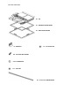
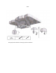
PACKAGED HARDWARE X 1 LIFT X 1 MOVABLE CEILING FRAME X 1 FIXED CEILING FRAME X 4 BRACKETS x 8 10-32 LOCK NUT X 8 8-32 HALF INCH SCREWS X 24 #10 WASHERS X 8 10-32 NUT X 4 10-32 X 12” THREADED ROD
General Information: 1- The control panel must be installed or positioned in the way that the operator has a constant visual of the lift during its travel while installation, setting limit switches and regular use. 2- The projector lift and other equipment may only be installed when the installer is working on a rigid and stable platform. 3- It is allowed to mount (1) piece of equipment, keeping the allowed maximum load of 25 lbs.
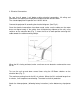
Steps for a Standard Installation: 1 - Determine Projector Location Location of the ceiling opening will depend on the projector being used. Projectors equipped with a zoom lens can focus the intended image size through a range of distances of several feet in variation. For this reason the exact distance, projector to screen surface, need only be held within the particular focus range specified by the projector manufacturer for the intended screen size.
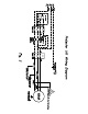
3- Electrical Connections. Be sure that all power is off before making electrical connections. All wiring and connections are required to comply with national and local electric codes. The standard projector lift operates on 110 VAC 60 Hz. Connect the projector lift according the electrical diagram. (See Fig 2.). Once the electrical connections have been made, make sure the cables on the motor drum are aligned neatly.
4- Installing the movable and fixed Ceiling Frame frames. The projector lift comes with a movable ceiling frame. This frame is attached to the bottom tray by four threaded rods that can be adjusted by cutting the rods to the desired height (Fig. 3). Depending on installation requirements, the provided movable ceiling frame may be covered with the original panel or another panel to match the existing ceiling (Fig. 4); or it may be removed entirely and replaced with a custom panel. Follow (Fig.
FIGURES
FIG 1. Use appropriate hardware according to specific installation.
FIG.
FIG.
FIG.
FIG.
FIG.
Fig 8