
User's Manual


Chapter 4 Register Descriptions
© National Instruments Corporation 4-49 VXI-MXI User Manual
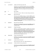
MXIbus Trigger Configuration Register
VXIbus Address: Base Address + 2E (hex)
Attributes: Read/Write
R/W
15 14 13 12 11 10 9
TRIG7EN TRIG6EN TRIG5EN TRIG4EN TRIG3EN TRIG2EN TRIG1EN TRIG0EN
8
R/W
7 65432
1
TRIG7DIR TRIG6DIR TRIG5DIR TRIG4DIR TRIG3DIR TRIG2DIR TRIG1DIR TRIG0DIR
0
This register maps the VXIbus TTL Trigger lines to and from the Trigger In and Trigger Out
SMB connectors on the front panel of the VXI-MXI. These bits are cleared on a hard reset.
Bit Mnemonic Description
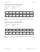
15-8r/w TRIG[7-0]EN Trigger Enable Bits
Setting these bits individually enable the corresponding VXIbus
TTL trigger lines to be mapped to the Trigger Out SMB connector
or from the Trigger In SMB connector on the front panel as
specified by the corresponding TRIGxDIR bit. Clearing these bits
disables the mapping of the trigger lines to the front panel SMB
connectors.
7-0r/w TRIG[7-0]DIR Trigger Direction Bits
If the TRIGxEN bit is clear, this bit has no meaning. If TRIGxEN
is set, this bit controls the routing of TTL trigger lines 7 to 0.
If this bit is set, TTL trigger lines 7 to 0 are driven by the signal
received on the front panel Trigger In SMB connector. If this bit is
clear, TTL trigger lines 7 to 0 are driven out of the mainframe
through the Trigger Out SMB on the front panel. This bit is
cleared on a hard reset.
TRIGxEN TRIGxDIR Routing
0 X Disabled
10
TTL TRIG X drives TRIG OUT
SMB
1 TRIG IN SMB drives TTL TRIG
X