
User manual


Chapter 5 Register Descriptions
VXI-MXI-2 User Manual 5-42 © National Instruments Corporation
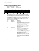
VXI-MXI-2 Trigger Control Register (VMTCR)
VXIbus Configuration Offset: 2E (hex)
Attributes: Read/Write 16, 8-bit accessible
15 14 13 12 11 10 9 8
TRIGEN[7] TRIGEN[6] TRIGEN[5] TRIGEN[4] TRIGEN[3] TRIGEN[2] TRIGEN[1] TRIGEN[0]
76 54 321 0
TRIGDIR[7] TRIGDIR[6] TRIGDIR[5] TRIGDIR[4] TRIGDIR[3] TRIGDIR[2] TRIGDIR[1] TRIGDIR[0]
You can use this register to control the routing of the eight VXIbus TTL trigger lines
between the VXIbus and the two front-panel trigger SMB connectors. Any triggers that
the VXI-MXI-2 itself generates are driven on the VXIbus and must be routed to the TRG
OUT SMB through this register if the destination for the trigger is located on the TRG
OUT SMB. Likewise, the VXI-MXI-2 can sense triggers only from the VXIbus, so any
triggers originating on the TRG IN SMB that the VXI-MXI-2 must sense should be
routed through this register to the VXIbus.
Bit Mnemonic Description
15-8 TRIGEN[7:0] Trigger Enable
Setting these bits individually enables routing of
the eight VXIbus TTL trigger lines between the
VXIbus and the front-panel SMB connectors.
Any trigger line whose corresponding
TRIGEN[7:0] bit is clear is not routed. These
bits are cleared by a hard reset and are not
affected by a soft reset.
7-0 TRIGDIR[7:0] Trigger Direction
When the corresponding TRIGEN[7:0] bit is
clear, these bits are ignored. When the
corresponding TRIGEN[7:0] bit is set, these bits
control the direction that the trigger is routed.
The trigger is routed from the VXIbus to the
TRG OUT SMB connector when its
TRIGDIR[7:0] bit is 0 (outward), and from the
TRG IN SMB connector to the VXIbus when its
TRIGDIR[7:0] bit is 1 (inward). These bits are
cleared by a hard reset and are not affected by a
soft reset.