
User manual


Chapter 5 Register Descriptions
© National Instruments Corporation 5-55 VXI-MXI-2 User Manual
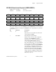
DMA Interrupt Enable Register (DMAIER)
VXIbus A24 or A32 Offset: 12 (hex)
Attributes: Read/Write 16, 8-bit accessible
15 14 13 12 11 10 9 8
0 0 0 0 DMAIEN 0 0 ENABLE
76 54 321 0
00 00 000 0
This register enables mapping of the DMA interrupt to the VXIbus. The interrupt can be
asserted only on the VXIbus and must be routed through the VXIbus Interrupt
Configuration Register (VICR) if the interrupt handler is located across the MXIbus. This
register is also used to re-arm the DMA interrupt after one has occurred by first disabling
the interrupt using this register, next clearing the DMA interrupt condition using either
the CLRDONE bit in the DMA Channel Operation Register (CHORx) or the
CLRDMAIE or CLRDONEIE bit in the DMA Channel Control Register (CHCRx), and
then re-enabling the interrupt using this register.
Bit Mnemonic Description
15-12 0 Reserved
These bits are reserved. Write each of these bits
with 0 when writing the DMAIER. The value
these bits return when read is meaningless.
11 DMAIEN DMA Interrupt Enable
This bit is used in combination with the
ENABLE bit to enable the DMA interrupt to be
mapped to the VXIbus. To enable the interrupt
write a 1 to both bits. To disable the interrupt
write a 1 to this bit and a 0 to the ENABLE bit.
This bit returns a 1 when read if the interrupt is
enabled and a 0 if the interrupt is disabled. The
interrupt is disabled on a hard reset and is not
affected by a soft reset.
10-9 0 Reserved
These bits are reserved. Write each of these bits
with 0 when writing the DMAIER. The value
these bits return when read is meaningless.