
User manual


Chapter 5 Register Descriptions
VXI-MXI-2 User Manual 5-62 © National Instruments Corporation
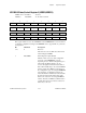
Notice that synchronous MXIbus burst cycles
cannot be used for the source or destination of a
DMA operation when both are located on the
MXIbus. In such a case, you must either program
this bit to use normal MXIbus block cycles, or
program the DMA Source Configuration
Register 2 (SCR2) and the DMA Destination
Configuration Register 2 (DCR2) to both use
single (non-block) cycles by clearing the
BLOCKEN bit. A hard reset causes block cycles
to the MXIbus from DMA Controller 2 to be
normal block cycles. This bit is not affected by
soft resets.
28 DMA1MBS DMA Controller 1 MXIbus Block Select
This bit performs the same function as
DMA2MBS but for DMA Controller 1.
27 DMAMB S/N* DMA MXIbus Block Synchronous/Normal*
When this bit is written with a 1, any
DMAxMBS bit that is also being written with a
1 is set (synchronous MXIbus burst cycles).
When this bit is written with a 0, any
DMAxMBS bit that is being written with a 1 is
cleared (normal MXIbus block cycles). The
value this bit returns when read is meaningless.
26-24 0 Reserved
These bits are reserved. Write these bits with 0
when writing to the SMCR.
23-22 1 Reserved
These bits are reserved. Write these bits with 1
when writing to the SMCR.
21 FAIR MXIbus Fair Requester
Setting this bit enables the MXIbus fair requester
protocol. When this bit is clear, the VXI-MXI-2
is an unfair requester on the MXIbus. Refer to
Chapter 7, VXIplug&play for the VXI-MXI-2,
or Appendix B, Programmable Configurations,
for more information on the Fair MXIbus
Requester protocol. On a hard reset, this bit is
initialized to the value stored in the onboard
EEPROM for this bit.