
User manual


Chapter 5 Register Descriptions
VXI-MXI-2 User Manual 5-82 © National Instruments Corporation
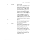
DMA Channel Status Register (CHSRx)
CHSR1 VXIbus A24 or A32 Offset: D3C (hex)
CHSR2 VXIbus A24 or A32 Offset: E3C (hex)
Attributes: Read Only 32, 16, 8-bit accessible
31 30 29 28 27 26 25 24
INT 0 0 0 0 0 DONE 0
23 22 21 20 19 18 17 16
00 00 000 0
15 14 13 12 11 10 9 8
ERROR SABORT 0 STOPS 0 0 XFERR 0
76 54 321 0
0 0 0 0 SERR[1] SERR[0] DERR[1] DERR[0]
This register provides status bits for DMA controller operations and error conditions.
Bit Mnemonic Description
31 INT DMA Interrupt
When this bit returns a 1, it indicates that the
corresponding DMA controller is asserting the
DMA interrupt.
30-26 0 Reserved
These bits are reserved. The value these bits
return when read is meaningless.
25 DONE DMA Done bit
This status bit is cleared when a DMA operation
is started and set when the operation is
terminated either successfully or by a stop or
error condition. This bit can be either polled or
used to generate an interrupt to signal when the
operation is complete. See the register
descriptions for the DMAICR, DMAIER,
DMAISIDR, and CHCRx for more information
about generating an interrupt on the DONE bit.
Once it is determined that the DMA operation is
done, the error condition bits in this register