
User manual


Chapter 6 System Configuration
© National Instruments Corporation 6-3 VXI-MXI-2 User Manual
Level 1
Level 2
MXIbus
Device
MXIbus
Device
VXIbus
Mainframe
VXI-MXI-2
VXI-MXI-2
VXIbus
Mainframe
VXI-MXI-2
VXIbus
Mainframe
VXI-MXI-2
VXI-MXI-2
VXI-MXI-2
Root
Multiframe
Resource
Manager
VXIbus
Mainframe
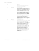
Figure 6-2. VXIbus/MXIbus System with Multiframe RM in a VXIbus Mainframe
The recommended way to set up your system is to fill up Level 1
MXIbus links before adding additional levels. System performance
decreases as you increase the number of levels to the system because
each level requires additional signal conversion. Also keep in mind
these basic rules for VXI-MXI-2 installation as you decide where to
install your VXI-MXI-2 interfaces:
• The VMEbus bus timeout unit must be on a VXI-MXI-2.
• Multiple VXI-MXI-2 interfaces in a mainframe must be in
adjacent slots.
The address mapping windows on the VXI-MXI-2 can be configured to
have a Base/Size format or a High/Low format. The CMODE bit in the
VXI-MXI-2 Control Register (VMCR) selects which format the
mapping windows use.
Base/Size Configuration Format
Each address mapping window on a VXI-MXI-2 interface has Base and
Size parameters associated with it when the CMODE bit in the
VXI-MXI-2 Control Register (VMCR) is cleared. The Base bits define
the base address for the window, and the Size bits indicate the number
of Base bits that are significant. Replacing the insignificant bits with