
User manual


Chapter 6 System Configuration
VXI-MXI-2 User Manual 6-6 © National Instruments Corporation
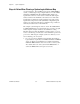
Steps to Follow When Planning a System Logical Address Map
As system integrator, when installing devices in the VXIbus/MXIbus
system, you must assign a range of logical addresses for each VXIbus
mainframe and MXIbus link. The multiframe RM configures the
logical address windows of each device to include the static logical
addresses it finds in the mainframe, and returns an error if the static
logical address assignments prevent assignment of an entire system
logical address map. Devices with dynamically configurable logical
addresses are assigned logical addresses within the range of addresses
defined by the static devices in the mainframe.
The example system in Figure 6-5 has two levels. The VXIbus RM is
in VXIbus Mainframe #1. Use the following steps to develop a logical
address map. The example worksheets show numbers for using
Base/Size window formats. For High/Low format systems, you do not
need to round the range of addresses for each mainframe up to the next
power of two. Following the example system are worksheets you can
use for analyzing your own system.
1. Lay out your system configuration and determine the number of
logical addresses required by each VXIbus mainframe and MXIbus
device. See Figure 6-5 and Table 6-2 for examples. Identify the
multiframe RM and label its host device as the root of the system.
Also identify the levels of the system and the MXIbus links on
each level. MXIbus links cannot span across levels.