
User manual


Chapter 6 System Configuration
© National Instruments Corporation 6-9 VXI-MXI-2 User Manual
For the example system, MXIbus #3 is a second-level MXIbus link
and it is connected to VXIbus Mainframe #3. We filled out the
worksheet in Figure 6-10 for MXIbus #3 and entered the results
into the worksheet for MXIbus #1 (Figure 6-8) under the device
VXIbus Mainframe #3. MXIbus #3 needs 32 logical addresses and
the devices in VXIbus Mainframe #3 need eight logical addresses.
The sum of these numbers is 40, which rounds up to 64.
5. Determine the total number of logical addresses required by each
MXIbus link by adding the numbers adjacent to the “*” symbols
and entering that number in the appropriate space at the bottom of
the worksheet. If you are using the Base/Size window format,
round the number to the highest power of two and enter it into the
appropriate space on the worksheet. Place these numbers in the
appropriate spaces on the worksheet for the next highest-level
device to which the MXIbus link is connected.
In the example system, MXIbus #1 requires 101 logical addresses
(found at the bottom of Figure 6-8) and MXIbus #2 requires eight
logical addresses (found at the bottom of Figure 6-9). We placed
these numbers in the corresponding spaces in Figure 6-7.
6. Add up the total number of logical addresses required for the
system (at the bottom of Figure 6-7). Round this number up to the
highest power of two if you are using Base/Size formats. The result
should be equal to or less than 256. If the number is greater than
256, you must reorganize your devices and reconfigure the system.
In the example system, this number equals 256, therefore the
configuration is acceptable.
7. If you are using Base/Size parameters, determine the Size field of
the range for each device and MXIbus link and insert that value in
the corresponding locations of the worksheets. When you round up
the number of logical addresses required to 2
x
,
Size = 8 – X.
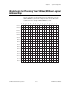
8. Determine the range of addresses that will be occupied by the root
device and each first-level device and MXIbus link. For Base/Size
systems, use the Logical Address Map Diagram shown in
Figure 6-6 to visualize the logical address map for the system.
Each square in this diagram represents one logical address. The
maximum number of logical addresses in a system is 256 and
address ranges are assigned in blocks divisible by a power of two.
Refer to Table 6-1 and Figure 6-4 for example logical address
allocations for different Size values.