
User manual


Chapter 6 System Configuration
VXI-MXI-2 User Manual 6-24 © National Instruments Corporation
BFFF-B000
AFFF-A000
9FFF-9000
8FFF-8000
7FFF-7000
6FFF-6000
5FFF-5000
4FFF-4000
3FFF-3000
2FFF-2000
1FFF-1000
0FFF-0000
Size = 2
Size = 3
Size = 4
Size = 5 Size = 6
Size = 7
Size = 1
Size = 0
F00 E00 D00 C00 B00 A00 900 800 700 600 500 400 300 200 100 000
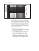
Figure 6-18. A16 Space Allocations for all Size Values
To plan the A16 address map, you will follow procedures similar to
those for planning the logical address space address map. Determine
the amount of A16 space required by each device; if you are using
Base/Size windowing formats, round that amount up to the next address
break listed in Table 6-3. Next, assign the A16 space, starting with the
root device and working down the VXIbus/MXIbus system tree. To
assist you in configuring the A16 window map on the VXI-MXI-2
interfaces in your system, the following pages include worksheets, an
address map diagram, and an example.
The following steps are used in the example:
1. Identify the RM Mainframe and the MXIbus levels of your system.
Determine the amount of A16 space required by each MXIbus
device. See Figure 6-18 and Table 6-4.
2. Fill out the RM Mainframe information in Figure 6-21. In this
example, the RM Mainframe needs 16 KB of A16 space.
3. Next, analyze the first-level MXIbus links and complete a
worksheet for each link. Figure 6-22 is the worksheet for
MXIbus #1, which includes MXIbus Device A, MXIbus Device B,
VXIbus Mainframe #2, and VXIbus Mainframe #3. MXIbus
Device A needs 512 B of A16 space. We fill in the worksheet
accordingly. MXIbus Device B and VXIbus Mainframe #2 do not
need any A16 space, so we put zeros in the worksheet for these