
User manual


Chapter 6 System Configuration
© National Instruments Corporation 6-41 VXI-MXI-2 User Manual
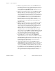
Table 6-5. Logical Address Assignments for Example VXIbus/MXIbus System
Device
Logical Address
Assignments
VXIbus Mainframe #1
Multiframe RM
VXI-MXI-2 on MXIbus #1
VXI-MXI-2 on MXIbus #2
0
2
4
MXIbus Device A E0
MXIbus Device B E4
VXIbus Mainframe #2
VXI-MXI-2 C0
VXIbus Mainframe #3
VXI-MXI-2 on MXIbus #1
VXI-MXI-2 on MXIbus #3
80
82
VXIbus Mainframe #4
VXI-MXI-2 A0
VXIbus Mainframe #5
VXI-MXI-2 B0
VXIbus Mainframe #6
VXI-MXI-2 10
The RM performs the following steps:
1. Scans logical addresses (0 to FF) and identifies all devices in
VXIbus Mainframe #1. Finds the VXI-MXI-2 interfaces at logical
addresses 2 and 4 and moves DC devices to the lowest unused
logical addresses (for example, 1, 3, 5, 6).
2. Enables the logical address window of the VXI-MXI-2 found at
logical address 2 for the entire outward mapping range of 0 to FF.
Scans all logical addresses, skipping all previously encountered
devices, and finds the VXI-MXI-2 in VXIbus Mainframe #3, the
VXI-MXI-2 in VXIbus Mainframe #2, MXIbus Device A, and
MXIbus Device B.
3. Enables the logical address window of the VXI-MXI-2 in VXIbus
Mainframe #3 for the entire inward mapping range of 0 to FF.
Scans all logical addresses, skipping all previously encountered
devices, and finds the VXI-MXI-2 at logical address 82. Finds the
Slot 0 device and uses it to move all DC devices in VXIbus
Mainframe #3 to the lowest unused logical addresses (for example,
81, 83, 84, 85).