
User manual


Appendix E Configuring a Two-Frame System
VXI-MXI-2 User Manual E-2 © National Instruments Corporation
Frame BFrame A
Slot 0 Device
VXI-MXI-2,
Slot 0
VXI-MXI-2,
non-Slot 0
bus
NATIONAL
INSTRUMENTS
®
bus
NATIONAL
INSTRUMENTS
®
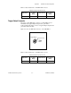
Figure E-1. A Two-Frame VXI System
In the example shown in Figure E-1, Frame A contains a VXI-MXI-2
configured as a non-Slot 0 device. It is logical address 1 and maps
CLK10 from the VXIbus to the MXIbus. Frame B contains a Slot 0
VXI-MXI-2. It is logical address 80 (hex) and maps CLK10 from the
MXIbus to the VXIbus.
Figure E-2 points out which hardware switches you need to change on
a C-size VXI-MXI-2 in either Frame A or Frame B of a two-frame VXI
system. Refer to Figure E-3 if you are using VXI-MXI-2/B modules.