
User manual


Appendix E Configuring a Two-Frame System
© National Instruments Corporation E-5 VXI-MXI-2 User Manual
VXIbus Logical Address
Frame A contains logical addresses in the range of 0 to 7F hex. The
Resource Manager must be logical address 0. The VXI-MXI-2 has
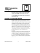
logical address 1, which is the default logical address. Figure E-4a
shows the switch setting for logical address 1 on a C-size VXI-MXI-2.
See Figure E-5a if you have a VXI-MXI-2/B. Ensure that no other
devices in that frame have either of these logical addresses. In addition,
no devices in Frame A should have logical addresses of 80 hex or
above (except for FF hex).
Frame B contains logical addresses from 80 hex to FE hex. The
VXI-MXI-2 in Frame B is logical address 80 hex, as shown in
Figure E-4b for a C-size VXI-MXI-2, or in Figure E-5b for a
VXI-MXI-2/B. Make sure that no other devices in Frame B have
logical addresses of 80 hex or below.
a. Switch Set to Logical Address 1 (Default)
Push up for logic 1
Push down for logic 0
LOGICAL ADDRESS
SWITCH
U43
12345678
Shown at default
setting of Logical
Address 1
b. Switch Set to Logical Address Hex 80
Push up for logic 1
Push down for logic 0
LOGICAL ADDRESS
SWITCH
U43
Shown at default
setting of Logical
Address 1
12345678
Figure E-4. Logical Address Selection on a C-Size VXI-MXI-2