
User manual


Appendix E Configuring a Two-Frame System
VXI-MXI-2 User Manual E-6 © National Instruments Corporation
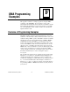
Figure E-5 shows switch settings for logical address hex 1 and 80 on a
VXI-MXI-2/B.
a. Switch Set to Logical Address 1 (Default)
b. Switch Set to Logical Address Hex 80
1 2345678
1 2345678
U20U20
Figure E-5. Logical Address Selection on a VXI-MXI-2/B
VXIbus CLK10 Routing for a Two-Frame System
The VXI-MXI-2 in Frame A routes CLK10 from the VXIbus to the
MXIbus. The Slot 0 device in Frame A is responsible for generating
CLK10 in that frame.
The VXI-MXI-2 in Frame B routes CLK10 from the MXIbus to the
VXIbus, which allows CLK10 to be synchronous between the two
frames.
Notice that the VXI-MXI-2 in Frame B must be the Slot 0 device in
that frame. Otherwise, it could not drive CLK10 on the backplane.