
User manual


Appendix E Configuring a Two-Frame System
VXI-MXI-2 User Manual E-8 © National Instruments Corporation
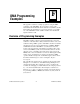
W3
S7
From onboard oscillator
From SMB (S3 must be set to "IN")
From MXIbusReceive CLK10 from MXIbus
Figure E-8. CLK10 Generated from MXIbus on a C-Size VXI-MXI-2
W1
ON
BRD
SMB
MXI
S1MBCLK10
IN OUT
Figure E-9. CLK10 Generated from MXIbus on a VXI-MXI-2/B
VXIbus Slot 0
The default setting of the VXI-MXI-2 is to automatically detect if it is
installed in Slot 0. With automatic detection, you can install the
VXI-MXI-2 in any slot of a VXIbus mainframe. In the two-frame
system described in this appendix, the VXI-MXI-2 is installed in Slot 0
in Frame B, but in a different slot in Frame A. You could also install
both in Slot 0 of their respective mainframes, or both in slots other than
Slot 0. However, CLK10 will not be synchronous between the two
frames if the VXI-MXI-2 configured to receive MXIbus CLK10 is not
installed in Slot 0.
MXIbus System Controller
The default setting of the VXI-MXI-2 is to automatically detect from
the MXIbus cable if it is the MXIbus System Controller. With
automatic detection, you can connect the cable in either direction.
Notice that one end of the cable is labeled to designate it as the end to
attach to the MXIbus System Controller. The VXI-MXI-2 you connect
to the labeled end of the cable will take on the responsibilities of the
MXIbus System Controller.