
User manual


Appendix F DMA Programming Examples
© National Instruments Corporation F-5 VXI-MXI-2 User Manual
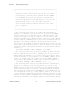
/************************************************************
* *
* Operation Termination: This section waits for the DMA *
* operation to complete. It is important that the *
* operation complete before either using the data that *
* is being sent to the destination or reprogramming any *
* of the DMA registers for another operation. *
* *
***********************************************************/
/* The following do-while loop waits for the DMA operation to
complete by polling for the DONE bit in CHSR1 to be 1. After
leaving this loop, the DMA operation has completed either
successfully or due to an error. */
do {
read(A24, A24BASE + CHSR1, LONGWORD, value);
} while((value & 0x02000000) == 0);
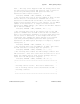
/* The following if statement checks if any errors occurred during
the DMA operation by checking the state of the ERROR bit that was
read from CHSR1 when the DONE bit became 1. If the expression is
false, the DMA operation completed successfully and the data at
the destination can now be used. If the expression is true, the
SERR[1:0] and DERR[1:0] bits of CHSR1 should be checked to
determine what type of error occurred. */
if (value & 0x00008000) {
/* The DMA operation encountered an error. */
}
Example 2: DMA Operation with Interrupt
This example is similar to Example 1 in that it programs DMA
controller 1 to perform the same data transfer from the source on the
VMEbus to the destination on the MXIbus. The source is located in
A24 space beginning at address location 200000 hex. VMEbus 32-bit
block cycles are used to read data from the source. The destination is
located in A32 space beginning at address location 40000000 hex.
MXIbus 32-bit synchronous burst cycles are used to write data to the
destination.