
User manual


Chapter 3 VXI-MXI-2 Configuration and Installation
VXI-MXI-2 User Manual 3-4 © National Instruments Corporation
You can change the logical address of the VXI-MXI-2 by changing the
setting of the 8-bit DIP switch labeled LOGICAL ADDRESS SWITCH
(location designator U43) on the panel. The down position of the DIP
switch corresponds to a logic value of 0 and the up position
corresponds to a logic value of 1. Verify that the VXI-MXI-2 does not
have the same logical address as any other statically configured
VXIbus device in your system. Remember that logical addresses hex 0
and FF are not allowed for the VXI-MXI-2. Also, when setting logical
addresses, keep in mind the grouping requirements set by the system
hierarchy. See Chapter 6, System Configuration, or VXI-6, VXIbus
Mainframe Extender Specification, for more information on setting
logical addresses on a multimainframe hierarchy.
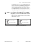
Figure 3-2 shows switch settings for logical address hex 1 and C0.
a. Switch Set to Logical Address 1 (Default)
Push up for logic 1
Push down for logic 0
LOGICAL ADDRESS
SWITCH
U43
12345678
12345678
Shown at default
setting of Logical
Address 1
b. Switch Set to Logical Address Hex C0
Push up for logic 1
Push down for logic 0
LOGICAL ADDRESS
SWITCH
U43
Shown at default
setting of Logical
Address 1
Figure 3-2. Logical Address Selection