
User manual


Chapter 3 VXI-MXI-2 Configuration and Installation
VXI-MXI-2 User Manual 3-6 © National Instruments Corporation
When the VXI-MXI-2 is installed in Slot 0, it becomes the VMEbus
System Controller. In this role, it has VMEbus Data Transfer Bus
Arbiter circuitry that accepts bus requests on all four VMEbus request
levels, prioritizes the requests, and grants the bus to the highest priority
requester. As VMEbus System Controller, the VXI-MXI-2 also drives
the 16 MHz VMEbus system clock by an onboard 16 MHz oscillator.
As required by the VXIbus specification, the VXI-MXI-2 drives the
10 MHz signal CLK10 on a differential ECL output when installed in
Slot 0. When not installed in Slot 0, the VXI-MXI-2 only receives the
CLK10 signal.
VXIbus Local Bus
If you will be installing more than one VXI-MXI-2 in a single VXIbus
mainframe, you must configure the boards to use the local bus. The
VXI-MXI-2 uses the local bus to pass a signal to the other VXI-MXI-2
modules in the mainframe to disable the VMEbus bus timeout unit
(BTO) during cycles that map to the MXIbus. Because the local bus is
used, you need to install all VXI-MXI-2 modules for a single
mainframe in adjacent slots.
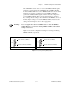
You will use two switches on the VXI-MXI-2 to select its position in
relation to any other VXI-MXI-2 module in the mainframe. Use switch
S9 when there is a VXI-MXI-2 to the right (higher numbered slot). Use
S8 when there is a VXI-MXI-2 to the left (lower numbered slot).
Figure 3-4 shows four configuration settings for a VXI-MXI-2.
Figure 3-4a illustrates the default setting, which is for a single
VXI-MXI-2 in a mainframe. Use the setting in Figure 3-4b for the
VXI-MXI-2 located to the left of all others. Figure 3-4c shows the
setting to use if the VXI-MXI-2 is between two others. Use the setting
of Figure 3-4d for the VXI-MXI-2 located to the right of all others.