
User manual


Chapter 3 VXI-MXI-2 Configuration and Installation
© National Instruments Corporation 3-7 VXI-MXI-2 User Manual
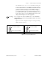
a. Single VXI-MXI-2 in Mainframe (Default)
b. Leftmost VXI-MXI-2 in Mainframe
c.VXI-MXI-2 between Two Others
d. Rightmost VXI-MXI-2 in Mainframe
S8
S9
No Yes
VXI-MXI to left
VXI-MXI to right
S8
S9
No Yes
VXI-MXI to left
VXI-MXI to right
S8
S9
No Yes
VXI-MXI to left
VXI-MXI to right
S8
S9
No Yes
VXI-MXI to left
VXI-MXI to right
Figure 3-4. VXIbus Local Bus Configuration
VXIbus CLK10 Routing
When the VXI-MXI-2 is installed in Slot 0 of your mainframe, it
supplies the VXIbus CLK10 signal. The VXI-MXI-2 can use three
different sources to generate this signal: an onboard oscillator, the
external CLK SMB connector, and the MXIbus CLK10 signal.
Use the three-position jumper W3 to select these options, as shown
in Figure 3-5.
Notice that Figures 3-5b and 3-5c also show switches S3 and S7,
respectively. You must configure these switches as shown when using
the corresponding CLK10 source setting of W3.