
User manual


© National Instruments Corporation 4-1 VXI-MXI-2 User Manual
VXI-MXI-2/B
Configuration
and Installation
4
Chapter
This chapter contains the instructions to configure and install the
VXI-MXI-2/B module. If you have a C-size VXI-MXI-2, see
Chapter 3, VXI-MXI-2 Configuration and Installation.
Some features of the VXI-MXI-2/B are not configurable with onboard
switches or jumpers but are instead programmable. Refer to Chapter 7,
VXIplug&play for the VXI-MXI-2, or Appendix B, Programmable
Configurations, for a description of the programmable features.
Warning: Electrostatic discharge can damage several components on your
VXI-MXI-2/B module. To avoid such damage in handling the module,
touch the antistatic plastic package to a metal part of your VXI chassis
before removing the VXI-MXI-2/B from the package.
Configure the VXI-MXI-2/B
This section describes how to configure the following options on the
VXI-MXI-2/B.
• VXIbus logical address
• VXIbus Slot 0/Non-Slot 0
• VXIbus local bus
• VXIbus CLK10 routing
• Trigger input termination
• MXIbus termination
• Configuration EEPROM
• Onboard DRAM
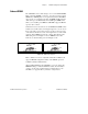
Figure 4-1 shows the location and factory-default settings of most of
the configuration switches and jumpers on the VXI-MXI-2/B.