
User manual


Chapter 5 Register Descriptions
VXI-MXI-2 User Manual 5-30 © National Instruments Corporation
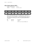
VXI-MXI-2 Control Register (VMCR)
VXIbus Configuration Offset: 20 (hex)
Attributes: Write Only 16, 8-bit accessible
15 14 13 12 11 10 9 8
0 CMODE ECLEN[1] ECLDIR[1] ECLEN[0] ECLDIR[0] DSYSFAIL DSYSRST
76 54 321 0
0 0 0 0 0 0 0 INTLCK
This VXI-MXI-2 specific register provides control bits for various operations.
Bit Mnemonic Description
15 0 Reserved
This bit is reserved. Write a 0 when writing to
this bit.
14 CMODE Comparison Mode
This bit selects the range comparison mode for
the Extender Logical Address (VWR0), A16
(VWR1), A24 (VWR2), and A32 (VWR3)
Window Registers. If CMODE is cleared, a
Base/Size range comparison is used to determine
the range of addresses in the windows, as
described in the VWRx register descriptions. If
CMODE is set, an upper and lower bound is
used to determine the range of addresses in the
windows. The upper eight bits of each VWRx
register form the upper bound (HIGH[7:0]),
while the lower eight bits form the lower bound
(LOW[7:0]). The LOW[7:0] bits define the
lower limit of the range of MXIbus addresses
that map into the VXIbus, while the HIGH[7:0]
bits define the upper limit. As with the normal
comparison mode, any address that is not in the
range will map in the opposite direction. When
HIGH[7:0] > [range] ≥ LOW[7:0], a MXIbus
cycle within the range maps to the VXIbus,
while a VXIbus cycle out of that range maps to
the MXIbus. When LOW[7:0] > [range] ≥
HIGH[7:0], a VXIbus cycle within the range