
User`s manual


www.vxitech.com
Tektronix to VXI Technology Cross-Ref. Guide 15
Tektronix
VX4380
VXI Technology
SM4380
Application Program
VXI Driver (Tek)
c:\vxipnp\<frwk>\bin\tkvx430x0_32.dll
plug&play
VISA Library
visa.dll
VX4380 Specific Commands
Application Program
VISA Library
visa.dll
VXI Driver (VTI)
c:\vxipnp\<frwk>\bin\tkvx430x0_31.dll
Tek to SMIP/SMIP Translation
plug&play
II
SM4380 Specific Commands
TPS Utilizing PNP Driver Calls
Compiled Driver Written Using VISA
Insturment Commands Using VISA
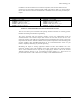
FIGURE 1-1: TEKTRONIX VX4380 TO VXI TECHNOLOGY SM4380
EXCEPTIONS
There will be some exceptions for cases where it is not possible for VXI Technology to emulate
all functions of all Tektronix drivers. Exceptions are listed on an instrument by instrument basis.
One global exception is manufacturer ID's and model codes. The VTI manufacturer and model
codes will be returned as opposed to the Tektronix info.
MAINTAINING SIGNAL INTEGRITY THROUGH THE SWITCHING PATH
All SMIP II series switch modules are designed with over a decade of experience in signal switch
development and are optimized to preserve signal integrity. All switch modules employ multi-
layer PCB designs with extensive ground planes and shielding where appropriate with relays
selected to maximize signal integrity. Signal ground planes are isolated from the control circuit
grounds and signal paths are designed to minimize crosstalk between channels. To further
minimize any digital noise, the control circuitry goes into a quiescent state when not processing
commands, making it possible to switch low-level signals. Mating connector shrouds are also
available to permit cable harnesses to be crimped, soldered or connected via terminal blocks,
allowing the user to select the method of cabling most suitable for their application.
It is important to note that all shields on switch cards are brought out to the front panel. The intent
is for the user to provide a path from ground to the shield pins to ensure signal integrity. If these
shield pins are left floating, they can become a potential source of noise. All pinout reference
tables indicate the location of the shield pins.