
User's Manual


Maintenance
VX1410A & VX1420A IntelliFrame Mainframe Instruction Manual
8–19
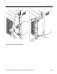
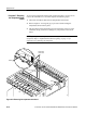
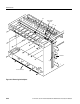
To remove the backplane, perform Procedures 1, 2, 3, and 4 on page, beginning
on page 8–5. Refer to Figure 8–15 and then complete the following steps:
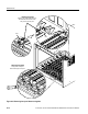
1. Remove all the modules that are from installed in the mainframe.
2. Disconnect the ribbon cable 0J4 located on the right end (viewed from the
rear of the instrument) of the backplane.
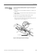
NOTE. Note which connector the power switch and SysReset cables are
connected to on the backplane circuit board.
3. Disconnect the power switch cable at J22 (or from J23) at the top of the
backplane circuit board.
4. Disconnect the SysReset cable (if attached) at J29 at the top of the backplane
circuit board.
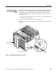
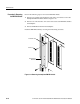
5. From the rear of the mainframe, remove the five 6-32 screws on the top of
the backplane, the seven 6-32 screws from the center, and the five 6-32
screws from the bottom.
6. After removing all screws from the backplane, remove the backplane from
the mainframe by sliding it out of the right side.
Install the backplane by reversing the disassembly procedure.
NOTE. If the backplane was replaced, the mainframe must be recalibrated. Refer
to Adjustment Procedure 5 on page 7–1.
Procedure 10: Removing
the Backplane