
User's Manual


VT1536A Isolated Digital Input/Output SCP 11
• INP:THR:LEV? returns a numeric value which is one of 5, 12, 24, 48 or
0 (zero) where zero means that the channel is configured as an output
and non-zero values indicate the input threshold in volts.
Note If an invalid switch combination is set, INP:THR:LEV? will NOT return a
value and will generate the error 3105 "Invalid SCP switch setting". This
error will also be generated when
*RST is executed. Channels associated
with this error will behave as input channels with unknown threshold levels.
To query the threshold level on the second channel at SCP position 2 send:
INP:THR:LEV? (@117)
query 2nd chan on SCP pos. 2
enter statement here
returns 0 | 5 | 12 | 24 | 48
Configuring Input
Channel Polarity
To configure input channel polarity use the command:
INPut:POLarity INVerted | NORMal,
(@<ch_list>)
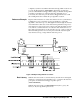
To configure the first 2 channels on an VT1536A in SCP position 4 to input
Normal polarity (opto on=logical 1) and its next 2 channels to input inverted
polarity (opto off=logical 1)send:
INP:POL NORM,(@132,133)
NORM is *RST default
INP:POL INV,(@134,135)
There is also the query form; INPut:POLarity? (@<channel>), where
<channel> must specify a single channel.
INP:POL? returns NORM | INV.
Note The INPut:POL command will generate the error 3107, "Channel data
direction conflicts with command" if any channel in <ch_list> is configured
as an output.
Setting Debounce Time For a description of the debounce function See “Debounce Function” on
page 8. The VT1536A has two debounce timers. One for the lower four
channels, and one for the upper four channels. To set the debounce timers
use the command:
INPut:DEBounce:TIME <time>,(@<ch_list>)
• <time> can be one of 16 possible numeric values or MIN and MAX:
Note Because the clock that generates the debounce period is asynchronous to
your input signal, there is a region of uncertainty relative to the nominal
debounce period selected. This is reflected in the “Minimum” and
“Maximum” debounce period columns in
Table 2.