
User`s manual

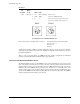

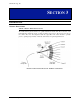
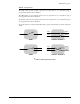
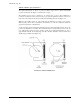

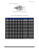
Table Of Contents

VXI Technology, Inc.
28 SM8000 Series Operation
OPERATION
SM8001 / SM8002 - Multi-Channel Switches
When controlling multi-switch modules, the operation is quite similar to that of any other SMIP II
family product, but the data sent is operated on a little bit differently. The SM8000 must be
configured to control the multi-switch device on one of four ports. This is done at the factory with
hardware selectable jumpers. Once configured for multi-switch operation, the control of the
switch is accomplished by writing to the appropriate Relay Register. Relay registers 02 through 08
are used to control the multi-switch modules. The value written to the multi-switch module is
dependent on the type/size of the switch.
For example, if the switch is a 1xN switch, writing the value of 00h to Relay Register 02 would
optically connect the switches input to the first output. A write of 0Ah would connect the input to
the 11
th
output, and so on. Data lines 4 through 0 are used to transfer data to the switch modules.
The Busy signal from the optical module may be monitored to indicate when the optical module
has completed moving to the commanded switch setting. The optical module also generates an
Error signal that may be monitored. This signal might be used to provide a confidence check that
the module is being controlled properly.
Resetting the Switch
When the switch is in reset (park) position, channel zero, or optical off, there is no optical
connection to any output channel. Set the switch to the reset position to prevent optical data from
passing through the switch, or to reset the stepper motor. During a reset operation, optical noise
may appear on various output channels as the armature rotates.
There are two ways to reset the switch. The first is to cycle power to return the switch to the reset
position. The second is to return the switch to the reset position using a sequence of writes to the
SMIP module rather than interrupting the supply power. See the example of a multi-switch reset
write sequence as described later in this manual. The BUSY output remains high until the reset
operation is complete and the device is ready to receive additional instructions.
Relay Registers - Output Channel Selection
The following sections show information to select channels for the SM8001/8002 through the
relay registers. Each configuration section includes an optical input/output relation figure,
followed by a table that lists the control codes for channel selection.