CT-400 CHASSIS THIRTEEN-SLOT VXIBUS CHASSIS USER’S MANUAL P/N: 82-0050-000 Released December 21, 2007 VXI Technology, Inc. 2031 Main Street Irvine, CA 92614-6509 (949) 955-1894 .
www.vxitech.com TABLE OF CONTENTS INTRODUCTION Certification .........................................................................................................................................................5 Warranty ..............................................................................................................................................................5 Limitation of Warranty .......................................................................................................
VXI Technology, Inc. SECTION 3 ...................................................................................................................................................................47 OPERATION ..............................................................................................................................................................47 Introduction...................................................................................................................................
www.vxitech.com CERTIFICATION VXI Technology, Inc. (VTI) certifies that this product met its published specifications at the time of shipment from the factory. VTI further certifies that its calibration measurements are traceable to the United States National Institute of Standards and Technology (formerly National Bureau of Standards), to the extent allowed by that organization’s calibration facility, and to the calibration facilities of other International Standards Organization members.
VXI Technology, Inc. DECLARATION OF CONFORMITY Declaration of Conformity According to ISO/IEC Guide 22 and EN 45014 MANUFACTURER’S NAME VXI Technology, Inc. MANUFACTURER’S ADDRESS 2031 Main Street Irvine, California 92614-6509 PRODUCT NAME Thirteen-Slot VXIbus Chassis MODEL NUMBER(S) CT-400 PRODUCT OPTIONS All PRODUCT CONFIGURATIONS All VXI Technology, Inc.
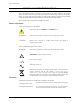
www.vxitech.com GENERAL SAFETY INSTRUCTIONS Review the following safety precautions to avoid bodily injury and/or damage to the product. These precautions must be observed during all phases of operation or service of this product. Failure to comply with these precautions, or with specific warnings elsewhere in this manual, violates safety standards of design, manufacture, and intended use of the product. Service should only be performed by qualified personnel.
VXI Technology, Inc. WARNINGS (CONT.) Use Proper Fuse Avoid Electric Shock 8 To avoid fire hazard, only use the type and rating fuse specified for this product. To avoid electric shock or fire hazard, do not operate this product with the covers removed. Do not connect or disconnect any cable, probes, test leads, etc. while they are connected to a voltage source. Remove all power and unplug unit before performing any service. Service should only be performed by qualified personnel.
www.vxitech.com SUPPORT RESOURCES Support resources for this product are available on the Internet and at VXI Technology customer support centers. VXI Technology World Headquarters VXI Technology, Inc. 2031 Main Street Irvine, CA 92614-6509 Phone: (949) 955-1894 Fax: (949) 955-3041 VXI Technology Cleveland Instrument Division 5425 Warner Road Suite 13 Valley View, OH 44125 Phone: (216) 447-8950 Fax: (216) 447-8951 VXI Technology Lake Stevens Instrument Division VXI Technology, Inc.
VXI Technology, Inc.
www.vxitech.com SECTION 1 INTRODUCTION INTRODUCTION This section contains a general description of operating features of the CT-400. A list of mainframe features follows the description, which is then followed by a brief discussion of the options available for the CT-400.
VXI Technology, Inc. GENERAL DESCRIPTION The CT-400 mainframe is a C-size, thirteen-slot, VXIbus compatible mainframe that conforms fully to VXIbus Specification Revision 1.4. The mainframe employs a multi-layer backplane to ensure premium VXIbus and VMEbus performance and provides all power supplies required by the VXIbus specification. The CT-400 mainframe contains thirteen slots in the card cage, twelve of which are available for use by VXIbus compatible instruments.
www.vxitech.com CT-400 MAINFRAME FEATURES FRONT PANEL FEATURES POWER SWITCH Feature 1 When elevated, the mainframe is in standby mode, where power is supplied to the mainframe, but not to the VXI modules. When depressed, power is supplied to both mainframe and VXI modules. VOLTAGE MONITOR INDICATORS Indicates whether specific backplane voltages are within specifications. See Feature 2 Figure 1-3 for details.
VXI Technology, Inc. VOLTAGE INDICATOR LEDS The power supply lines are monitored and displayed on the front panel, providing information pertaining to the chassis operational status. Voltage Monitor LEDs Green : Within Voltage Specifications Not Lit : Under Voltage Red : Over Voltage 0 +5V CT-400 SERIES VXI MAINFRAME 1 -5.
www.vxitech.com REAR PANEL MONITOR / CONTROL CONNECTOR The 25-pin Monitor/Control Connector (see Figure 1-2) provides access to the backplane voltages and other signals. The following table shows a pinout/signal list along with a brief description of each. Refer to the pin locations in Figure 1-4.
VXI Technology, Inc. CT-400 SPECIFICATIONS GENERAL SPECIFICATIONS SIZE 16.7" (424.18 mm) W x 14.00" (355.60 mm) H x 25.00" D (635.00 mm) Thirteen C-size VXIbus card slots WEIGHT < 50 lb (11.3 kg) VXIBUS VERSION 1.4 MTBF 100,000 hr MTTR 5 min ENVIRONMENTAL SPECIFICATIONS OPERATING LOCATION This chassis should be operated indoors in a controlled environment, protected from exposure to the elements (i.e. direct sunlight, precipitation, wind, etc.
www.vxitech.com POWER SPECIFICATIONS POWER Available Useable DC SUPPLY VOLTAGE 1630 W 1000 W A total of 1000 W may be supplied to the modules with the following maximum currents: Voltage +5 V -5.2 V -2 V +12 V -12 V +24 V -24 V Peak Current (IMP) 80 A 60 A 30 A 17 A 17 A 12 A 12 A Dynamic Current (IMD) 15 A 10 A 5A 3A 3A 4A 4A OUTPUT VOLTAGE Voltage Allowed Variation +5 V -5.2 V -2 V +12 V -12 V +24 V -24 V +0.25 V / -0.125 V -0.26 V / +0.125 V -0.10 V / +0.72 V +0.60 V / +0.36 V -0.60 V / +0.
VXI Technology, Inc. TOP VIEW 0.805 (20.440) 24.900 (632.46) REAR VIEW 16.699 (424.15) 15A T 250 ! F200 (VAC) REMOVE COVER TO SERVICE AIR FILTER J200 100 - 240 VAC 15 A MAX. 47 -63 Hz WARNING - DO NOT REMOV E THIS PO WER M ODULE WHILE THIS INSTRUM ENT HAS AC POWER APP LIE D ! WARNING - THE GROUNDING CONNECTION IN THE POWE R CORD MUST BE CONNECTED TO ENSURE PROTECTION FROM ELECTRICAL S HOCK. ! WARNING - TO AVOID ELE CTRICAL SHOCK, DISCONNE CT AC POW ER CORD PRIOR TO REPLACING FUS E.
www.vxitech.com CT-400 OPTIONS OPTIONS ADJUSTABLE RACK MOUNT FLANGES WITH HANDLES These allow the mainframe to be accommodated into any depth rack - either OPTION 100 recessed in the rack up to 10 inches (25.4 cm) or extended out from the rack up to 5 inches (12.7 cm). VXIPLUG&PLAY RACK MOUNT KIT This allows the CT-400 to be used with VXIplug&play adapters and interfaces. OPTION 101 RACK MOUNT SLIDES Mounts the CT-400 in the rack while allowing access by sliding the unit.
VXI Technology, Inc.
www.vxitech.
VXI Technology, Inc.
www.vxitech.
VXI Technology, Inc.
www.vxitech.com SECTION 2 INSTALLATION INTRODUCTION This section includes instructions on CT-400 configuration and installation. When the CT-400 is unpacked from its shipping carton, the contents should include the following items: (1) CT-400 Thirteen-Slot Mainframe (1) CT-400 User’s Manual (this manual) (1) Power cord All components should be immediately inspected for damage upon receipt of the unit. The power cord is the only way to disconnect the CT-400 mainframe from ac power.
VXI Technology, Inc. CONNECTING THE MAINFRAME TO EARTH GROUND The CT-400 is configured at the factory for 115 V ac, 60 Hz. The supplied power cord grounding conductor provides adequate grounding for this voltage and frequency level. However, if the CT-400 is to run at anything higher than 63 Hz, the mainframe MUST be connected to earth ground at the mainframe as follows: 1) Connect a 16 AWG (or larger) wire to the ground terminal located on the rear panel (this connection is marked by a symbol).
www.vxitech.com the shield guides are set back 1" from the card guides metal strip down center of shield guide all plastic card guide Front of Mainframe FIGURE 2-2: DETAIL - CARD GUIDE / SHIELD GUIDE INSTALLING THE CARD SHIELD OPTION Optional card shields are available for improved EMI/RFI performance (see the CT-400 Options table). Each card shield option is installed in the shorter card shield guide, to the left of each card guide.
VXI Technology, Inc. BENCH-TOP CT-400 USE OVERVIEW If the CT-400 is to be used as a bench-top mainframe, ensure that adequate spacing is provided for the mainframe for cooling purposes as delineated in the previous section. The mainframe should be placed in a climate-controlled area, away from such elements as precipitation, direct sunlight, etc. Once installed, the mainframe is not intended to be mobile.
www.vxitech.com RACK MOUNTING THE CT-400 OVERVIEW This section contains instructions for installing the different rack mount options available for the CT-400 mainframe. After installation of the rack mount options, the mainframe can then be mounted into an EIA rack. Three different rack mounting options exist for the CT-400 and are listed below.
VXI Technology, Inc. OPTION 100 - ADJUSTABLE RACK MOUNT FLANGES WITH HANDLES This procedure provides the necessary instructions for installing the adjustable rack mount flanges with handles.
www.vxitech.
VXI Technology, Inc. OPTION 101 - VXIPLUG&PLAY RACK MOUNT KIT This procedure provides the necessary instructions for installing a VXIplug&play rack mount kit.
www.vxitech.
VXI Technology, Inc. OPTION 102 - RACK MOUNT SLIDES Rack mount slides allow the end user the ability to easily access the mainframe after it has been installed into an EIA rack. This option may be used in conjunction with either Option 100 or 101, or maybe installed and used independently. (Refer to the previous section for Option 100 and 101 installation instructions.
www.vxitech.
VXI Technology, Inc. ADDITIONAL RACK MOUNT OPTIONS OVERVIEW This section contains the procedures for installing additional options for the CT-400. The available rack mounting options are: Option 103 - Transparent Front Door The transparent front door provides protection of instruments and cables while permitting the viewing of VXIbus instrument annunciators. Option 104 - Hinged Custom Front Panel The customizable front panel hinges down and mounts on the front of the CT-400.
www.vxitech.
VXI Technology, Inc. OPTION 103 - TRANSPARENT FRONT DOOR INSTALLATION PROCEDURE This kit requires Option 100 be installed prior to its installation. Refer to the previous section on Option 100 for installation instructions. Required Tools 1) #2 Phillips Screwdriver Parts List Item# 1 2 3 4 5 6 Qty 2 8 1 2 1 1 Description Screw, 8-32 x 3/8" Phillips, Sq Cone Sems Zinc Screw, 8-32 x 3/8" Flat Head Phillips, Zinc Flush Pull Latch, 2.0" Dia.
www.vxitech.
VXI Technology, Inc. OPTION 104 - HINGED CUSTOM FRONT PANEL INSTALLATION PROCEDURE This kit includes the hardware found in Option 100 as well as the hardware necessary to install the hinged custom front panel.
www.vxitech.com 7) Locate the adjustable hinges. Attach the hinges to the front door using 8-32 x 3/8" pan head Phillips screws. Attach the door to the lower support bracket using the same hardware. 8) Attach the door to the support hinges using a nylon washer and an 8-32 x 3/8" pan head Phillips screws. 11 6.
VXI Technology, Inc. OPTION 105/106 - 1U/2U CABLE TRAYS INSTALLATION PROCEDURE The 1U/2U cable trays make organizing the cabling associated with the mainframe and modules more manageable. The cable tray is the same both the 1U and 2U version, with only the height of the rear panel differentiating between the two.
www.vxitech.
VXI Technology, Inc. INSTALLATION OF VXI MODULES OVERVIEW After the successful installation of rack mount accessories, the chassis is ready for installation of the VXIbus base units (i.e. an SMP1100, SMP1200, etc.). It is recommended that the instruments be installed after rack mount accessories have been installed to avoid any unnecessary physical strains that may be incurred during the installation of the accessories. Whether single- or doublewide, the process of installation is simple.
www.vxitech.com DISCONNECTING THE MAINFRAME To disconnect the CT-400 from its installation, simply follow the instructions below: 1) Place the mainframe in standby by depressing the power switch. 2) Remove the power cord from the mainframe to ensure that no power is running to the mainframe. 3) Remove all cabling associated with the VXI modules installed in the CT-400. 4) If the chassis is rack mounted, remove the chassis from the rack by removing the screws that attach the mainframe to the rack.
VXI Technology, Inc.
www.vxitech.com SECTION 3 OPERATION INTRODUCTION There are no operating instructions required for the CT-400 VXIbus mainframe. After the mainframe is installed, operation is completely transparent to the operator. Just plug in the instruments then power up the mainframe. The power supply lines and mainframe operation are monitored and displayed to provide user-feedback of correct operation. Additionally, the user can configure the CT-400 for remote power on operation if desired.
VXI Technology, Inc. CT-400 MONITOR BOARD The CT-400 Monitor board provides monitoring of the mainframe’s operation and environment. It provides the user with access to the seven VXIbus backplane voltages (to power external circuitry), access to the eight backplane TTL trigger lines (for input and output) and control over the unit’s cooling operation. The cooling operation can be selected with the three-position fan speed switch located on the Monitor board.
www.vxitech.com CT-400 MONITOR BOARD - SIGNALS Connector J210 AMBTEMPOUT – Analog output reflecting the temperature of the air entering the mainframe. This is a non-linearized signal. See Figure 3-3 for a voltage to temperature conversion. Voltage to Temperature Conversion Voltage (V) 20 15 10 5 0 0 10 20 30 40 50 60 70 80 Temperature (°C) Ambient Temp 0 °C 10 °C 20 °C 25 °C 30 °C AMBTEMPOUT 3.27 V 3.76 V 4.50 V 5.00 V 5.60 V Ambient Temp 40 °C 50 °C 60 °C 70 °C AMBTEMPOUT 7.19 V 9.44 V 12.
VXI Technology, Inc. FANSPEEDLOW* - This low true open collector output signals a power supply overtemperature condition. This fault occurs when either of the two fans supplying air to the VXI instruments speed drops below 1000 RPM. This signal is pulled up to +5 V with a 4.7k resistor internally. FANTACH1 - This is a TTL compatible pulse output, whose period is a function of fan number 1 supplying air to the VXI instruments. This signal provides five positive edges per revolution of the fan.
www.vxitech.com SECTION 4 SERVICE INFORMATION INTRODUCTION The CT-400 should operate without the need for service, except for regular cleaning of the air filter elements. The cleaning schedule is dependant upon the amount of dust in the air, how many hours the unit is operated and how much airflow is required to adequately cool the installed instruments. Note Service should only be performed by qualified personnel.
VXI Technology, Inc. CLEANING THE AIR FILTERS Two air filters are present on the CT-400: a module fan filter and a power supply fan filter. Keeping these filters clean is important in maintaining an adequate air flow through the mainframe and over the power supply. The air filters can be cleaned in the following manner. Cleaning the Power Supply Fan Filter 1) Power off the mainframe and remove the power cord. 2) Locate the metal cover plate to the right of the power cord connector and fuse.
www.vxitech.com Cleaning the Module Fan Filter 1) Power off the mainframe and remove the power cord. 2) Locate the metal air filter cover at the bottom half of the mainframe. 3) Remove the four screws holding it in place and remove the cover and the filter element. 4) Blow the dust and dirt out of the air filter element using compressed air or, optionally, use water and a mild soap.
VXI Technology, Inc. POWER SUPPLY REPLACEMENT PROCEDURE In the event that the cooling fans or power supply must be replaced, they are contained in a single, easy to remove module. Replacement of the power supply can be accomplished as follows: 1) Power off the mainframe and remove the power cord. 2) Locate four thumbscrews on the rear of the mainframe and loosen all four. 3) Locate two handles on the power supply and firmly pull the module straight back and remove.
VXI Technology, Inc.
VXI Technology, Inc. INDEX A P air filters .............................................................................26, 51, 52 cleaning ..............................................................................52, 53 airflow ......................................................................... 12, 16, 26, 51 peak current.................................................................................... 17 power supply .........................................................................