
User's Manual


www.vxitech.com
CT-400 Introduction 13
CT-400 MAINFRAME FEATURES
FRONT PANEL FEATURES
POWER SWITCH
Feature 1
When elevated, the mainframe is in standby mode, where power is supplied to
the mainframe, but not to the VXI modules.
When depressed, power is supplied to both mainframe and VXI modules.
VOLTAGE MONITOR INDICATORS
Feature 2
Indicates whether specific backplane voltages are within specifications. See
Figure 1-3 for details.
REAR PANEL FEATURES
MODULE FAN FILTER
Feature 3
Replaceable component that filters the air that cools the plug-in modules.
CHASSIS GROUND TERMINAL
Feature 4
Used to electrical ground the mainframe.
J200 CONNECTOR
Feature 5
AC power receptacle.
F200 CONNECTOR
Feature 6
Fuse location.
J210 CONNECTOR
Feature 7
Monitor / Control Connector.
POWER SUPPLY FAN FILTER
Feature 8
Replaceable component that filters the air that cools the power supply.
MONITOR BOARD / J211 CONNECTOR
Feature 9
Provides monitoring of the mainframe’s operation and environment.
(See
Section 1 for more details.)
POWER SUPPLY
Feature 10
Replaceable power supply unit.
J211
J210
PWS
PWS
PWS
PWS
FAN
FAN SPEED
HIGH
VAR
LOW
AMB
TEM P
PWR
VOLT
CUR
SPEED
TEM P
!
WARNING - DO NOT REM OVE T HIS P OWER M ODULE
WHILE THIS INSTRUMENT HAS AC POWER APPLIED
!
WARNIN G -
THE GROUN DING CONNECTION IN THE
POWER CORD MUST BE CONNECTED TO ENSURE
PROTECTI ON FROM ELE CTRIC AL SHOCK .
!
WARNING - TO AVOID ELECTRICAL SHOCK, DISCONNECT
AC POWER CORD PRIOR TO REPLACING FUSE.
CAUTION -
FOR CONTINUED FIRE PROTECTION
REPLACE ONLY WITH A FUSE OF THE CORRECT
VOLTA GE AND R ATING.
J200
100 - 240 VAC
15 A MAX.
47 -63 Hz
REMOV E COVER TO
SERVICE AIR FILTER
J201
MONITOR / CONTROL
F200
15A T 250 (VAC)
01
Voltage Monitors
+5V +12V +24V +5V Stby
-5.2V -12 V -24V -2V
CT-400 SERIES
VXI MAINFRAME
1 2 3 4 5 6 7 8 9 101112
1 2
5
6 7 8 9
10
4
3
bus
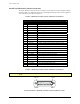
F
IGURE 1-2: MAINFRAME FEATURE LOCATIONS