
User's Manual


VXI Technology, Inc.
42 CT-400 Installation
OPTION 105/106 - 1U/2U CABLE TRAYS INSTALLATION PROCEDURE
The 1U/2U cable trays make organizing the cabling associated with the mainframe and modules
more manageable. The cable tray is the same both the 1U and 2U version, with only the height of
the rear panel differentiating between the two.
Required Tools
1) #2 Phillips Screw Driver
Parts List
Item# Qty Description VTI P/N
1 5 Screw, 6-32 x 3/8" Pan Head Ph, Sq Cone Sems Zinc 37-0028-037
2 1
Rear Panel, Wire Tray, User Modifiable, 1U
-or-
Rear Panel, Wire Tray, User Modifiable, 2U
41-0227-000
41-0227-001
3 1 Cable Tray, 1U / 2U Deep 41-0228-000
Assembly Procedure
1) Lay the mainframe on a protected work surface on its long side with the voltage monitor
LEDs of the mainframe facing front with the power switch toward the top.
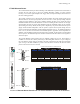
2) Locate the cable tray. Attach the rear panel (either 1U or 2U) using the screws provided with
kit. See
Figure 2-8 for screw locations.
3) Locate the ten screws at the bottom of the side plates and remove. See
Figure 2-8 for location.
4) Attach the cable tray to the mainframe using the screws removed in Step 3. This process is
most easily accomplished with the mainframe oriented upside-down.