
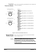
Universal Remote User Manual

Field Wiring 49Chapter 2
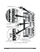
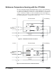
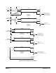
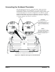
Connecting the On-Board Thermistor
The following figures show how to use the VT1422A to make temperature
measurements using the on-board Thermistor or a remote reference sensor.
The Thermistor is used for reference junction temperature sensing for thermocouple
measurements. Figure 2-12 shows the configuration for the VT1422A’s Spring
Terminal Module, Figure 2-6 shows the configuration for the Screw Terminal
Module. See “Reference Temperature Sensing with the VT1422A” on page 44 for
a schematic diagram of the reference connections.
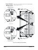
Under
C
ove
ON
BOARD
ON
BOARD
ON
BOARD
J1
J1
r
ON BOARD
PlacebothJ1jumpershereto
connect current source to
on-board thermistor RT1. Sense
RT1 by connecting any sense
channels to terminals HTS and
LTS.
REMote
Place both J1
j
umpers here to
route current source to terminals
HTI and LTI. Connect these
terminals to remote thermistor o
r
RTD. Sense with any sense
channel.
REM
REM
SCP 0
REM
J1
SCP 4
SCP 5 SCP 6
SCP 7
SCP 1
SCP 2
SCP 3
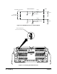
See Figure 2-13 on page 50 to remove the cover
Figure 2-12. Temperature Sensing for the Terminal Module