MN T-DPT-45¢" DPT Series Digital Paging Transmitter User Manual Sonic Sonia Technologies Corporation 310 Via Vera Cruz San Marcos, CA 92069 L DPT Version 2D
MN T-DPT-45¢" DPT-Series User Manual This manual covers the following products: Models: DPT-136 136-150MHz, 5W DPT-150 146-174MHz, SW DPT-218 218-230MHz, 2W DPT-260 260-280MHz, 2W DPT-450 450-470MHz, 2W Copyright © 1997 by Sonia Technologies Corporation. This manual is Copyrighted and may be reproduced for distribution with the DPT series of products as long as the manual remains int ass, in fis entirety, with all Copyright, intellectual property, and Trademark notices.
MN T-DPT-45¢ 1. Specifications Physical and Environmental Specifications Dimensions: Operating Temperature: Humidity: Vibration: Shock: RF I/O: General Electrical Specifications Power Supply: PLL step size: Frequency Stability: Power Consumption: Frequency range: Modulation: REF circuits no-tune bandwidth: Analog frequency response: Digital input: “ (export only) 50" x9.0" x15" -30 ta +60°C 95 % non-condensing 0.27 G (5 to 500 drop BNC female +12,5VDC + 10% 2 ppm. 1.5ppm optional.
MN T-DPT-45¢ 2. Introduction This Digital Paging Transmitter is a high performance transmitter capable of transmitting both digital and analog signals. It features: Both analog and digital inputs Data rates up to 4800bps Continuous duty operation at full power output High stability reference oscillator Synthesized frequency generation Easy configuration via a built-in RS-232 port Compact size and an easy fo use interface. Front panel status LED Built-in test signal generator. Fast transmit attack time.
MT-DPT-45§ POSTBAG. The formatted paging message is sent to the Digital Paging Transmitter for transmission over the air. Other manufacturers have paging encoders available with built in keypads, facilitating the entry of pages without requiring a dedicated computer.
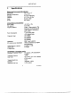
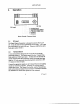
MT-DPT-458 3. Operation II Ti] B [EEE Out 5. Analog input prestidigitation select + 3 Transmit digital data © skyline =~ 1 Ground DC input Rear Panel Connections 3.1. DC input The Digital Paging Transmitter is designed to operate off of 12.5V DC. It may be used with any regulated DC power supply. A DC input jack is provided on the rear of the unit. The power cord for the unit is Sonia part number 5C201-6. 3.2.
MT-DPT-458" The 5 pins are defined as follows: Pin | Function Level 1 Ground/signal | Connect this to the signal ground of the paging common encoder. Z Keynote. This signal may be programmed 10 bs either active Activate this input to turn low or active high. The detente from the factory is active low. Open circuiting this will not cause the transmitter to key. It is a COS types level. A low must bs <.8V and a high must be greater than 3.5V. This pin may be driven by an RS-232 type signal.
MN T-DPT-45¢ Name Unction DB-9 Pin # TXD Transmit Serial Data from HO module 3 ta modem RXD Receive Serial Data from modem to 2 I/O module GND System Ground 5 Serial Interface Pin Assignments Pin Female Connector Most any terminal emulation program may be used to communicate with the Digital Paging Transmitter. Suitable programs for the [BM PC are Pro comm, Win comm, and Windows “Terminal” program.
KEY HIGH KEY LOW DATA+ DATA DATA MT-DPT-458 MHz. Makes the key line active high. Makes the key line active low This sets the DATA input to positive polarity (1 = +deviation, 0 = deviation} Sets the DATA input to negative polarity (1 = deviation, 0 = +deviation) This command is for testing purposes only. It causes the transmitter to key. The modulation wit be an internally generated 244Hz square wave, Do not apply external modulation when using this function.
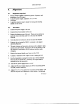
MT-DPT-450" 4. Alignment 4.1. Equipment required; « Service monitor capable of measuring power, frequency, and modulation of an FM signal » 2 amp DC power supply, adjustable DC o Volt meter » A spectrum analyzer may be handy for tuning and ensuring stability or the carrier. 42. Procedure 1. Connect the power supply to the unit 2. Connect the service monitor to the unit. 3. Remove the bottom cover of the unit. There are two screws on each side. two in the front, and two in the rear that must be removed. 4.
MN T-DPT-45¢ forth between adjusting the to achieve best results. The RF output power should be 5 watts or greater. Turn the DC power supply up to 12.5V Adjust the RF output using R84, to 5.0 watts or less (2 watts on unis above 200MHz), DO NOT LEAVE THE POWER CONTROL SET AT MAXIMUM! It must always be turned down some from its maximum power setting. Tightly re-adjust £70 and C65 for best efficiency and lowest harmonic output. A current draw of 1.25 amps at 5 watts RF output is normal. 1.
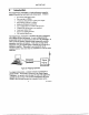
MN T-DPT-45¢' £3 Balance tern [3 prevision: 701 13 © TPS ca? Ll £78 crs = cio £9 Power Digital Paging Transmitter Test and Alignment Points DFT Version 20 Ere RF
MN T-DPT456" Sonia Technologies Corporation Limited Warranty Subject to the Limitations of Warranty and the Warranty Procedures, hereinafter set forth, Sonia Technologies Corporation (Sonia) hereby warrants this product to perform substantially in accordance with its specifications for a period of one year from the date of original purchase from Sonia.
MT-DPT-456 in materials or workmanship, or with respect tu any breach of any implied warranty applicable t this product. f. Sonia assumes po ability for consequential damages whatsoever.