Vzense DCAM550 ToF Camera User Manual DCAM550U DCAM550P 1
Table of Contents 1 2 3 4 5 6 General Information ............................................................................................ 4 1.1 Terms of Use ............................................................................................ 4 Precautions ........................................................................................................ 5 2.1 Safe Usage Instructions ........................................................................... 5 2.2 Power ...............
6.1.5 Standalone Mode Installation ....................................................... 25 6.2 Software Installation ............................................................................... 26 6.2.1 How to get .................................................................................... 26 6.2.2 Graphic Tool on windows .............................................................. 26 6.2.3 Frameviewer ................................................................................ 27 6.
1 General Information The purpose of this document is to familiarize the customer with the correct operation of the Vzense ToF DCAM550 products family. This document provides important information about the camera’s features, hardware specification, safe use of the camera, and installation procedures. DCAM550 product family is a series of products designed by Vzense company. It has two sub-series, DCAM550-U refers to the USB version, DCAM550-P refers to the Power over Ethernet version. 1.
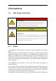
2 Precautions 2.1 Safe Usage Instructions DANGER Electric Shock Risk Non-standard and improper power supplies may result in fire and electric shock. You must confirm the camera power supply used that meets the Safety Extra Low Voltage(SELV) and Limited Power Supply (LPS) requirements. CAUTION Invisible Radiation This camera uses laser to work, improper use may damage the eye.
to customer at original cost. Below is the PoE+ injector available vendor list. Vendor Model Number H3C EWPAM2NPOE TP LINK TL-POE170S 2.3 Usage Don’t try to open the camera housing. Each camera has been calibrated at the factory to achieve precise measurements. Touching internal components may damage the camera and cause calibration data lost. Incorrect plugging in and unplugging of the camera’s power cable can damage the camera.
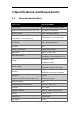
3 Specifications and Requirement 3.1 General Specifications Specification Vzense DCAM550 Technology ToF (Time-of-flight) Depth Camera Depth Sensor Resolution and Frame rate 640 x 480(VGA)@30FPS Output Formats Depth Sensor Field of View Depth & IR Map (RAW12) H-Horizontal, V-Vertical(degree) Typical: H-69°V-51° (customizable, up to H 120°V90°) Use Range 0.3m~6m(customizable) Accuracy <1% Power Consumption Average Max. 5W(Ref) Illumination 940nm ,2 x 2W Vcsel DCAM550-U: 65mm*65mm*52.
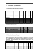
3.2 Electrical Specifications 3.2.1 Recommended Operating Conditions Parameter DC Power USB2.0 Digital I/O (Exposure_timing) Digital I/O (Ext_Trigger) RS485 Operating Temperature Operating humidity Storage humidity Storage temperature Symbol VDD USB Vout Conditions Min 11 4.75 Max 26 5.5 Units V V V 3.3 20 V -12 -20 20 20 -30 12 50 80 80 70 V °C % % °C Work mode Vin Ta Typ. 12 5 5 3.2.
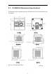
3.3 DCAM550-P Mechanical Specifications This drawing contains information about the dimensions and user mounting location of the ToF Camera. Front View Back View Bottom View Top View Left View Right View Fig. 3.
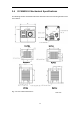
3.4 DCAM550-U Mechanical Specifications This drawing contains information about the dimensions and user mounting location of the ToF Camera. Front View Back View Bottom View Top View Left View Right View Fig. 3.
3.5 Optical Specifications 3.5.1 Field of View The field of view refers to the view angle of the ToF products. The TOF sensor’s aspect ratio is 4:3, typically the horizontal field of view is larger than the vertical field of view. The DFOV (see figure below) is the angle subtended by the diagonal of the camera sensor onto the center of the lens. The definition of HFOV and VFOV can be exchanged, i. e. we can rotate the camera sensor to have larger FOV at vertical direction.
3.6 Working Condition Requirements 3.6.1 Hardware Requirements DCAM550-U: TYPE A to TYPE A USB cable (Included in package) 6 pin cable which provide RS485, I/O signals. (Not included in package) DC Power Adaptor. (Included in package) DCAM550-P: CAT5 Ethernet cable (Included in package) 6 pin cable which provide power and interface with host. (Not included in package) DC Power Adaptor. (Included in package) Or PoE+ Power Supplier. (Not included in package) 3.6.
substantial, thermally conductive component that can act as a heat sink. Or a fan can be used to provide an air flow over the camera. 3.6.4 Coordinate of the Camera System There are two coordinate system need to be understood, one is camera coordinate system (CCS), one is world coordinate system (WCS). CCS: CCS describe the two-dimensional data, the origin of coordinates is the optic center. WCS: WCS describe the three-dimensional information.
4 Interface with Host DCAM550-U ToF Camera is equipped with Type-A, LED, 6pin connector, DC JACK at the back of its housing as shown in below figure. For more information about pin assignments and connector types, see the following sections. Fig. 4.1: Camera Connectors DCAM550-P ToF Camera is equipped with RJ45, LED, 6pin connector, IP reset button at the back of its housing as shown in below figure. For more information about pin assignments and connector types, see the following sections. Fig. 4.
4.1 6pin Connector The 6pin connector includes the one physical input signals and one physical output signal, RS485 signal. The pin assignments and pin numbering for the receptacle are as shown in below table. The connector of the camera is a Molex receptacle, part number 535170630. The recommended mating connector is a Molex plug, part number 511030600.
T1 T1 EXT_Trigger Exposure Exposure Camera Exposure The requirement to T1 should be from 100us to 2ms. Exposure_timing Pin Description This pin is an output indicates the whole exposure period of the camera. The internal circuit of this pin with a pull-up resistor 430Ω.The pull up voltage is 5V. At low level, the pull-down resistor is 100Ω. By default, the polarity is low level activated, which means a low-level signal indicates the exposure period.
4.4 LED indication An LED at the back side of the camera indicates the camera status.
Ethernet connection established, BLUE LED constantly on IP RESET, Press the IP RESET button for 5 seconds, PURPLE LED is on for 5 seconds and blink twice then the product reset itself. Firmware Upgrade, WHITE LED is on until firmware upgrade finished ToF driver Upgrade, GREEN LED blinking repeatedly 4.5 IP Reset Button for DCAM550-P A hidden button hole is for IP reset, a pin shall be used to press the button.
5 Principle of Time of Flight 5.1 Vzense ToF Principle Vzense DCAM710 product principle is based on range-gated imaging ToF solution, and the sensor inside is based on Panasonic CCD sensor MN34906. Fig. 9 5.2 Noise Factors 5.2.1 Ambient Light Because the ToF distance measurement relies on the reflection of light sent out by the camera, any additional light, e.g. artificial light sources or sunlight, may influence the measurement results.
To eliminate the multipath effect, you should: 1. Keep the camera working environment as clean as possible; 2. Avoid the camera be placed at concave forms environment, like corners of a room or inside of a narrow space; 3. Highly-reflective object shall be removed far away from the measurement target; 5.
6 Installation 6.1 Hardware Installation You have read and understood the warnings listed under "Precautions" on Chapter 2; To achieve reliable distance measurements, please follow below tips: Better not using the camera in strong sunlight. If have to, keep the ambient light below 50k Lux. Do NOT place any objects in the scene that are not part of your intended target, especially mirrors or other shiny surfaces/objects. Maintain a stable housing temperature during operation.
PC USB HUB ToF Camera Power Adaptor You can contact the Vzense team (info@vzense.com) for the external powered USB HUB. 6.1.3 100M Ethernet Installation (DCAM550-P Only) In this mode, the camera transmits the required data to host by Ethernet cable, so the power adaptor shall be used. The steps are as below: 1. Mount the camera in an appropriate fixture, e.g. a camera bracket; 2.
6.1.4 POE Mode Installation What is POE (Power Over Ethernet) Power over Ethernet (POE) is a technology that lets network cables carry electrical power. For example, a digital security camera normally requires two connections to be made when it is installed: A network connection, in order to be able to communicate with video recording and display equipment. A power connection, to deliver the electrical power the camera needs to operate.
distribution of network connections is simple and effective How to Upgrade to POE Adding POE to your network is straightforward, and there are two routes you can choose: A POE switch is a network switch that has Power over Ethernet injection built-in. Simply connect other network devices to the switch as normal, and the switch will detect whether they are POE-compatible and enable power automatically.
IEEE 802.3at-2009 standard also known as PoE+, which can provide up to 25.5W, or IEEE 802.3bt-2018 standard also known as PoE++, which can provide up to 60W. Otherwise the product may not work well at long range mode. We can provide optional PoE switch or PoE injector to our customers, please try to contact the sales for the quotation and more information. Steps to Setup PoE Mode As mentioned above, a PoE switch or PoE injector shall be in use to setup the PoE; The steps are as below: 1.
6.2 Software Installation 6.2.1 How to get Download or clone SDK project from our GitHub /Gitee: China:https://gitee.com/Vzense Oversea:https://github.com/Vzense Please chose the suitable version based on the product and system. Windows SDK, Linux SDK have different project repository. 6.2.2 Graphic Tool on windows Vense uTool is a graphic tool on windows for the all Vzense ToF products. Download or clone uTool evaluation tool from our GitHub /Gitee: China:https://gitee.
6.2.3 Frameviewer Frameviewer is an opensource application in SDK project that can guide user how to call the SDK APIs. It has a pre-build version app in Tools folder, the source code is in Samples folder. See the document for the details. 6.3 Firmware Upgrade Download the VzenseUpgradeTool from below link: China: https://gitee.com/Vzense/VzenseUpgradeTool Oversea: https://github.com/Vzense/VzenseUpgradeTool Please read the Vzense_UpgradeTool_User_Guide.pdf before upgrading firmware.
6.
DCAM550-P 6.5 Power Off: product do not have any power Broadcast: broadcast IP address, socket have not connected Connected: socket is connected, product can transfer image and answer host command Factory Reset: resume all data to factory setting TOF Driver Upgrade: product is in upgrading of TOF driver System Upgrade: product is in upgrading of firmware Software Command Set DCAM550 support different work mode like depth_30, IR_30, depth&IR_30. Three default range: range0(0.35m~1.
7 Features 7.1 Slave Trigger Mode At slave trigger mode, the DCAM550 product outputs image only at every trigger signal happens. Please refer to 4.1 6 Pin Connector for the requirement to the hardware trigger signal; Two ways can set the DCAM550 product at slave trigger mode: 1) Call API Ps2_SetSlaveModeEnabled(PsDeviceHandle device, uint32_t sessionIndex, bool bEnabled), before Ps2_StartStream(); This way requires calling the API every power cycle.
7.3 Wide Dynamic Range As mentioned above, Most of the ToF based 3D sensing technology has range limitation to nearest and furthest distance, due to the sensor saturation of weak light strength to far objects. One range mode of the Vzense DCAM550 camera can fulfill furthest distance be at most 5 times to nearest distance. For example, if the near limitation is 0.4m, then the furthest distance in this mode can reach about 2m. DISTANCE ERROR 0.025 0.02 0.015 0.01 0.
DISTANCE ERROR % Merge More Modes Into One 4 3.5 3 2.5 2 1.5 1 0.5 0 DISTANCE RANGE UNIT MM Please refer to Vzense_WDR_function_application_note.pdf implementation steps. 7.4 for the WDR Data Filtering In the software SDK and Frameviewer, we implemented data filtering to improve the depth data performance. The filtering algorithm includes: Median filtering; Gaussian filtering; Bilateral filtering; Timing filtering; Flying pixel removing; 7.
8 Camera Operation on Frameviewer Please refer to 6.2.1 for the SDK downloading. Function 2D image show Camera hardware information show Image store Depth 30 IR 30 Mode Switch Depth&IR 30 WDR Range Change Range 0-7 Pulse count Exposure parameter modify Gamma gain Filters switch IR_BG 8.
8.1.1 Image area Image area is the area of showing depth image, IR image. 8.1.2 Command and information area Frameviewer use CMD shell for camera control and information output. Like the image below: switch mode, change detect range, save 3D image and so on.
8.2 Connect devices Frameviewer will auto-connect the device, and output the base information on the window. 8.3 2D view The display area can show different type image. 8.3.1 Depth Image Depth image is covert to a rainbow image for real distance showing.
8.3.2 IR Image 8.4 3D image store When the depth image is showing, input ‘s/S’ to store the point cloud file. User can use CloudCompare to viewer the 3D image.
8.5 Camera Control 8.5.1 Mode switch DCAM550 can support Depth_30, IR_30, Depth&IR_30. Depth_30: depth image only in 30 fps. IR_30: IR image only in 30 fps. Depth&IR_30: depth and IR image all in 30 fps. 8.5.2 Range change By default, DCAM550 product has 4 different range modes calibrated, please see below table for more information: Range number Distance range Range 0 0.35m~1.5m Range 1 0.5m~2.8m Range 2 0.8m~4.4m Range 5 1.2m~6.
If you need other range mode requirement, you can ask Vzense team to do range customization, reasonable NRE fee will be charged. 8.6 WDR WDR mode can merge the multi-range image to extend the detect range. For example, if you want to get the distance from 0.35m to 4.4m, only one range mode can’t cover the whole distance. Use range 0 and 2 WDR can match this requirement.
Depth image in range 0: Depth image in range 2: 40
Merged depth image in WDR mode 41
9 DCAM550 Accessories and Package In package item list: DCAM550-U Item Part number 1 DCAM550-U 2 VZENSE-USB-TYPEA-CABLE 3 VZENSE-DC-12V3A-A 4 User Guide Description Quantity Vzense DCAM550-U Depth Camera Module 1 Dual Head Type A Lockable Cable 1 Power adaptor, DC 12V,3A 1 User guide 1 DCAM550-P Item Part number 1 DCAM550-P 2 VZENSE-LAN-CAT5e-CABLE 3 VZENSE-DC-12V3A-A 4 User Guide Description Vzense DCAM550-P Depth Camera Module RJ45, 100M Ethernet Cable Power adaptor, DC 12V,3A User guide Quantity 1 1
10 Customization Service Vzense team has rich experience in ToF product design and delivery, we welcome customer to send customization requirement besides the standard module. Reasonable NRE fee shall be charged depends on the requirement.