
DCAM550 ToF Camera User Manual -20210906

15
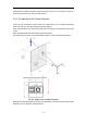
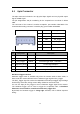
4.1 6pin Connector
The 6pin connector includes the one physical input signals and one physical output
signal, RS485 signal.
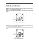
The pin assignments and pin numbering for the receptacle are as shown in below
table.
The connector of the camera is a Molex receptacle, part number 535170630. The
recommended mating connector is a Molex plug, part number 511030600.
Pin
Line Color
Designation
1
BN
RS485-A
2
GN
RS485-B
3
WH
Ext_Trigger
4
YE
Exposure_timing
5
BK
GND
6
RD
Ext_OUT
Pin Description
Pin
Designation
Direction
Description
1
RS485-A
I/O
RS485-A
2
RS485-B
I/O
RS485-B
3
Ext_Trigger
INPUT
External trigger input(3.3V-20V)
4
Exposure_timing
OUTPUT
Control signal output 1
5
GND
GND
System ground
6
Ext_OUT
OUTPUT
Control signal output from processor
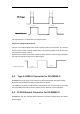
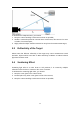
Hardware Trigger Function
Hardware trigger mode is available only when the camera works at slave mode, in
slave mode the camera will wait for the hardware trigger signal on Ext_Trigger.
The EXT_Trigger signal is to driver the MOSFET, External input trigger signal voltage
should range 3.3V-20V, driving current ability should be more than 5mA;
You can use input pin Ext_Trigger to send a hardware trigger signal to the camera.
The hardware trigger can be used to trigger the acquisition start. A hardware
debouncer circuit shall be considered on the EXT_Trigger line.
By default, the hardware trigger is rising edge activated, refer to below exposure
timing: