
Data Sheet

we-online.com
Würth Elektronik eiSos GmbH & Co. KG - Data Sheet - REV 1.0
13/31
WPMDH1102401 / 171012401
MagI³C Power Module
VDRM - Variable Step Down Regulator Module
DESIGN FLOW
Step 3. Select Input Capacitor (C
IN
)
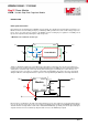
The MagI³C power module contains an internal 0.47μF input ceramic capacitor. Additional input capacitance is
required external to the MagI³C power module to handle the input ripple current of the application. This input
capacitance should be located as close as possible to the MagI³C power module. Input capacitor selection is
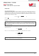
generally directed to satisfy the input ripple current requirements rather than by capacitance value. Worst case input
ripple current rating is dictated by the equation:
(9)
where
(As a point of reference, the worst case ripple current will occur when the module is presented with full load current
and when
).
If the system design requires a certain maximum value of input ripple voltage ΔV
IN
to be maintained then the following
equation may be used:
(10)
If ΔV
IN
is 1% of V
IN
for a 24V input to 12V output application this equals 240 mV and f
SW
= 400 kHz.
Recommended minimum input capacitance is 10µF X7R ceramic with a voltage rating at least 25% higher than
the maximum applied input voltage for the application. It is also recommended that attention be paid to the
voltage and temperature deratings of the capacitor selected. It should be noted that ripple current rating of
ceramic capacitors may be missing from the capacitor data sheet and you may have to contact the capacitor
manufacturer for this rating.
Additional bulk capacitance with higher ESR may be required to damp any resonant effects of the input
capacitance and parasitic inductance of the incoming supply lines.