
Data Sheet

we-online.com
Würth Elektronik eiSos GmbH & Co. KG - Data Sheet - REV 1.0
14/31
WPMDH1102401 / 171012401
MagI³C Power Module
VDRM - Variable Step Down Regulator Module
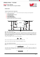
DESIGN FLOW
Step 4. Select Output Capacitor (C
OUT
)
None of the required output capacitance is integrated within the module. At a minimum, the output capacitor must
meet the worst case RMS current rating of
, as calculated in equation (8). Beyond that, additional
capacitance will reduce output ripple so long as the ESR is low enough to permit it. A minimum value of 10µF is
generally required. Please consider the derating of the nominal capacitance value dependent on the DC voltage
applied across it. Experimentation will be required if attempting to operate with a minimum value. Low ESR
capacitors, such as ceramic and polymer electrolytic capacitors are recommended.
Capacitance:
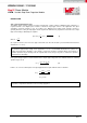
The following equation provides a good first pass approximation of C
OUT
for load transient requirements:
(11)
For example:
Solving:
ESR:
The ESR of the output capacitor affects the output voltage ripple. High ESR will result in larger V
OUT
peak-to-peak
ripple voltage. Furthermore, high output voltage ripple caused by excessive ESR can trigger the over-voltage
protection monitored at the FB pin. The ESR should be chosen to satisfy the maximum desired V
OUT
peak-to-peak
ripple voltage and to avoid over-voltage protection during normal operation. The following equations can be used:
(12)
where
(peak to peak inductor ripple current) is calculated using equation (8).
(13)
where A
FB
is the gain of the feedback network from V
OUT
to V
FB
at the switching frequency.
As worst case, assume the gain of A
FB
with the C
FF
capacitor at the switching frequency is 1.
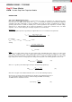
The selected output capacitor should have sufficient voltage and RMS current rating.
The RMS current is calculated as follows:
(14)