
Data Sheet

WPMDH1152401 / 171012402
MagI
3
C Power Module
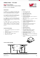
VDRM – Variable Step Down Regulator Module
we-online.com Würth Elektronik eiSos GmbH & Co. KG – Data Sheet Rev. 2.0
© December 2017 2/54
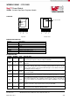
PACKAGE
Top View Bottom View
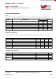
MARKING DESCRIPTION
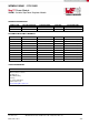
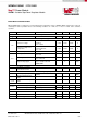
PIN DESCRIPTION
SYMBOL
NUMBER
TYPE
DESCRIPTION
VIN
1
Power
The supply input pin is a terminal for an unregulated input voltage source. It is required
to place the input capacitor nearby the VIN pin and PGND.
RON
2
Input
An external resistor from R
ON
to VIN pin sets the on-time and frequency of the
application.
EN
3
Input
Connecting this pin to GND disables the device. Connecting this pin to a voltage
higher than 1.18V typ. (but <6.5V) or leaving it floating enables the device. This pin
can be used in order to set an external UVLO through a resistor divider. If this pin is
left floating the device is always on.
AGND
4
Supply
The analog ground pin is the reference point for all stated voltages. It is internally
connected to PGND.
SS
5
Input
For the soft-start function there is an internal 8μA current source which charges an
external capacitor (C
SS
) to generate the soft-start. A minimum capacitance is required
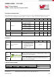
FB
6
Input
The feedback pin is internally connected to the regulation circuitry, the overvoltage and
short-circuit comparators. The regulation reference point is 0.8V at this input pin.
Connect the feedback resistor divider between the output and AGND to set the output
voltage.
VOUT
7
Power
The output voltage pin is connected to the internal inductor. For the best stability and
operation connect the output capacitor between this pin and PGND.
PGND
EP
Power
Exposed Pad – Main node for switch current of the internal low-side MOSFET. Used
as heat sink for power dissipation during operation.
Marking
Description
WE
Würth Elektronik tradename
Y
Year
M
Month
LLLL
Assembly lot code
G3
Lead finish code per Jedec Norm (green 3 mat sin)
WPMDH
Würth Part Description (part 1)
1152401JT
Würth Part Description (part 2)
RON
VIN
EN
AGND
SS
FB
VOUT
1 2 3 4 5
6
7
6 7
12345
6
7
67
Exposed Pad = PGND
EP
RON
VIN
EN
AGND
SS
FB
VOUT
YMLLLLG3
WPMDH
1152401JT