
Data Sheet


WPMDH1152401 / 171012402
MagI
3
C Power Module
VDRM – Variable Step Down Regulator Module
we-online.com Würth Elektronik eiSos GmbH & Co. KG – Data Sheet Rev. 2.0
© December 2017
21/54
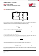
Step 4 Select output capacitor (C
OUT
)
L
C
OUT
V
IN
V
OUT
I
L
I
out
HS Mosfet
ESR
V
ESR
V
COUT
LS Mosfet
C
IN
R
Load
None of the required output capacitors are integrated within the module. A general recommendation in order to guarantee a
stable behavior is to place at least a capacitance of 10µF (MLCC recommended) at the output.
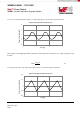
The output capacitor must meet the worst case RMS current rating, as calculated by equation (8):
I
C
OUTRMS
=
∆I
L
12
(8)
where ∆I
L
is the inductor current ripple calculated with the equation (9)
∆I
L
=
V
OUT
(V
IN
-V
OUT
)
f
SW
LV
IN
(9)
Selection by output voltage ripple requirements
The output capacitor should be selected in order to minimize the output voltage ripple and provide a stable voltage at the
output. Under steady state conditions, the voltage ripple observed at the output can be defined as:
V
OUT ripple
=∆I
L
∙ ESR+∆I
L
∙
1
8∙f
SW
∙C
OUT
(10)
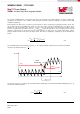
Very low ESR capacitors, like ceramic and polymer electrolytic, are recommended. If a low ESR capacitor is selected,
equation (10) can be simplified and a first condition for the minimum capacitance value can be derived:
C
OUT
≥
∆I
L
8 ∙ V
OUT ripple
∙ f
SW
(11)
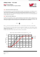
Beyond that, the additional capacitance will reduce the output voltage ripple as long as the ESR is low enough to permit it.
Please consider the derating of the nominal capacitance value due to temperature, aging and applied DC voltage (e.g.
MLCC X7R up to -50%).